Display system, display device, projection device and program

a technology of display device and projection device, applied in the field of display system, display device, projection device and program, can solve problems such as inability to perform a suitable display

Inactive Publication Date: 2015-06-04
CASIO COMPUTER CO LTD
View PDF9 Cites 38 Cited by
  • Summary
  • Abstract
  • Description
  • Claims
  • Application Information

AI Technical Summary

Benefits of technology

[0015]According to the present invention, it is possible to perform a display that is suitable to the traits of the object to be displayed.

Problems solved by technology

Therefore, in a situation such as several objects being interchangeably displayed on a single screen, the above configuration is not capable of performing a display that is suitable to the traits of the object to be displayed.

Method used


Image

  • Display system, display device, projection device and program
  • Display system, display device, projection device and program
  • Display system, display device, projection device and program

Examples


embodiment 1

[0029]100>

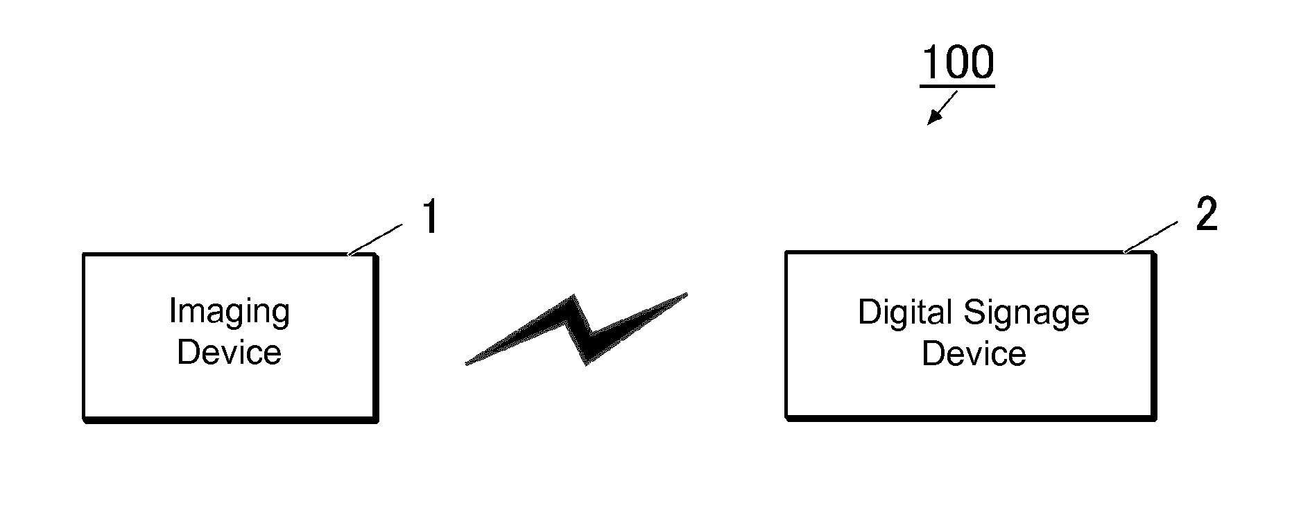
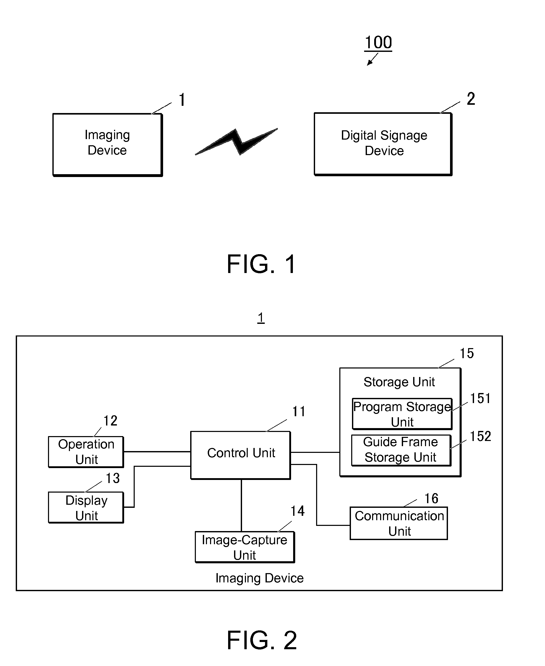
[0030]FIG. 1 is a block view of a schematic configuration of a display system 100 in Embodiment 1. The display system 100 is constituted of an imaging device 1 and a digital signage device 2, which can be connected to communicate with each other by a wired or wireless connection.

[0031]1>

[0032]FIG. 2 is a block view of a primary control configuration of the imaging device 1.

[0033]As shown in FIG. 2, the imaging device 1 includes a control unit 11, an operation unit 12, a display unit 13, an image-capture unit 14, a storage unit 15, a communication unit 16, and the like. As shown in FIG. 2, the operation unit 12, the display unit 13, the image-capture unit 14, the storage unit 15, and the communication unit 16 are connected to the control unit 11.

[0034]The control unit 11 has a CPU (central processing unit) that runs various types of programs stored in the storage unit 15 for controlling prescribed computations and units, and a memory that serves as the work area when the pr...

embodiment 2

[0084]Next, Embodiment 2 of the present invention will be described.

[0085]In Embodiment 1, an example was described in which the display area is determined in accordance with the traits of the object to be displayed in the digital signage device 2, but in Embodiment 2, the display area is determined by an imaging device 1.

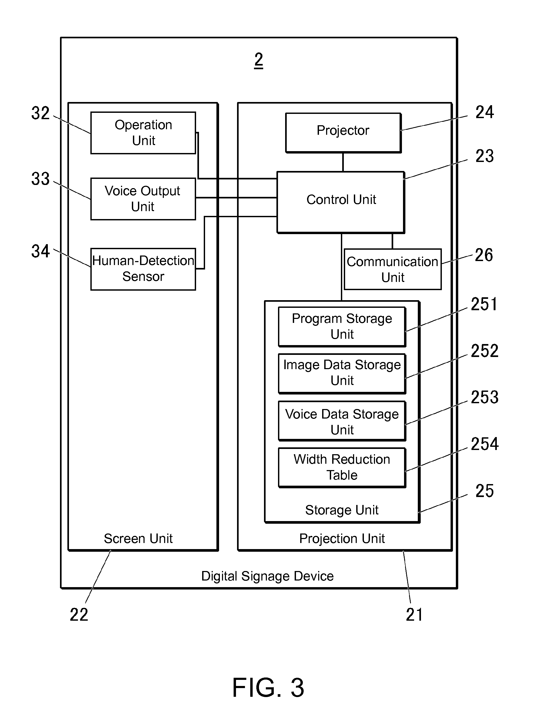
[0086]The configuration of a display system 100 in Embodiment 2 is substantially similar to the configuration explained using FIGS. 1-3 in Embodiment 1, but the contents stored in storage units 15 and 25 are different.

[0087]In Embodiment 2, a width reduction table 254 is stored in the storage unit 15 of the imaging device 1. A program storage unit 151 also stores programs for various types of processes such as a content imaging process B, described later, executed by a control unit 11 and the necessary data for executing these programs. In Embodiment 1, an image data storage unit 252 stored traits of the subject in correlation with the image of the human being, but...


PUM


Abstract

In an imaging device in a display system, a control unit recognizes human traits from an image of a human being that is an object to be displayed, which is obtained by photography. The image of the human being is correlated to information indicating the recognized traits and then transmitted to a digital signage device by a communication unit. In the digital signage device, the display area on an image display unit is determined in accordance with this information indicating the human traits that have been correlated to the image of the human being that is the object to be displayed, and the image of the human being that is the object to be displayed is modified so to be displayed in the determined display area, after which the modified image is displayed on the determined display area of the image display unit.

Description

BACKGROUND OF THE INVENTION[0001]1. Technical Field[0002]The present invention relates to a display system, display device, projection device and program.[0003]2. Background Art[0004]Conventionally, an image output device mounting apparatus is known to have: an image output device that connects to an image supplying device; a reflective member; and a screen. Output light that contains content and is outputted from the image output device is reflected by the reflective member, and the output light reflected from the reflective member is projected onto a screen formed in the shape of the content, thereby allowing for a heightened impression elicited by the viewer (see Patent Document 1, for example).RELATED ART DOCUMENT[0005]Patent Document[0006]Patent Document 1: Japanese Patent Application Laid-Open Publication No. 2011-150221.SUMMARY OF THE INVENTION[0007]With the image output device mounting apparatus described in Patent Document 1, however, the shape of the screen, which is the d...

Claims


Application Information

Patent Timeline
Patent Type & Authority Applications(United States)
IPC IPC(8): G06K9/00
CPCG06K9/00624G06T3/40G06T3/60G06V40/16G06V40/178
Inventor MURAYAMA, TAIGAHONJO, TAICHI
Owner CASIO COMPUTER CO LTD
Why Eureka
Try Eureka