
Bulk material handling system and method

a technology of bulk materials and handling systems, applied in the direction of mechanical conveyors, rolling carriages, loading/unloading, etc., can solve problems such as interruption of loading process, and achieve the effect of improving bulk material handling systems and

Active Publication Date: 2015-06-11
RAIL VEYOR TECH GLOBAL
View PDF1 Cites 2 Cited by
  • Summary
  • Abstract
  • Description
  • Claims
  • Application Information

AI Technical Summary

Benefits of technology

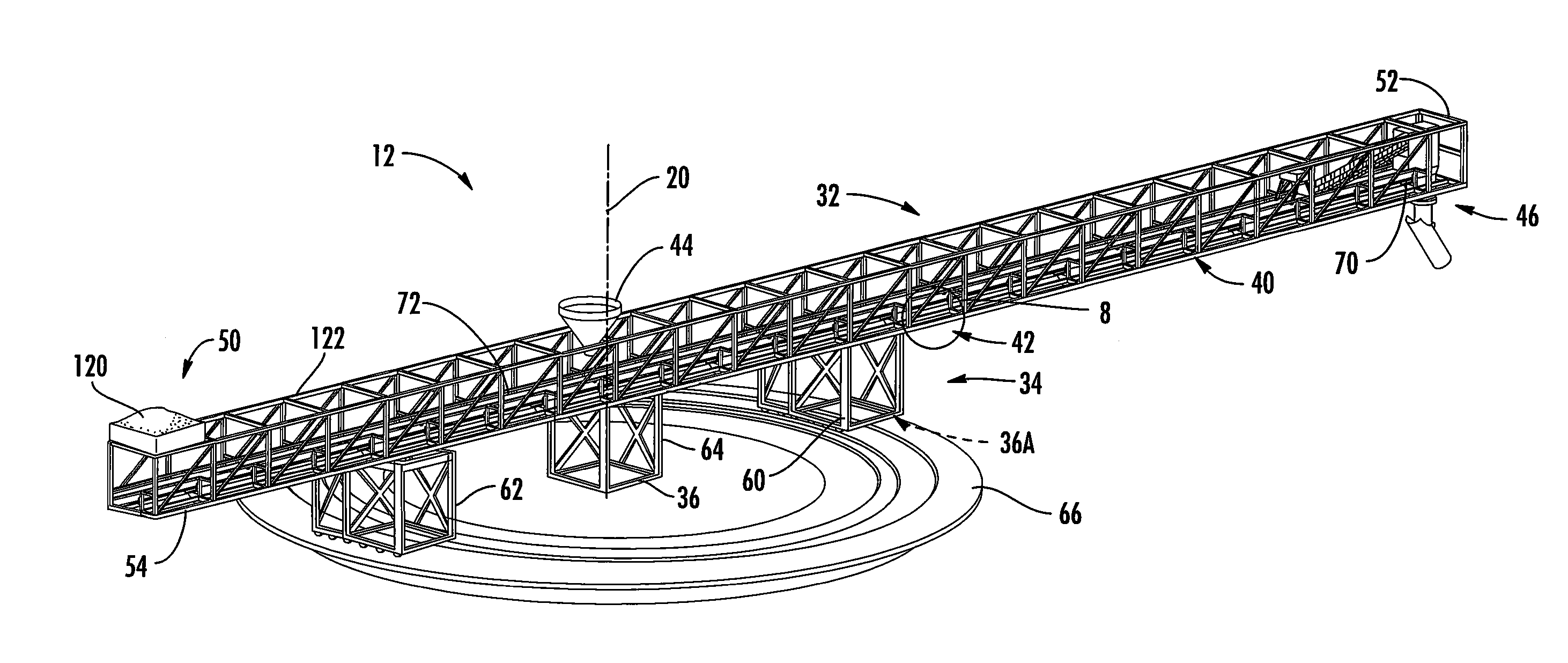
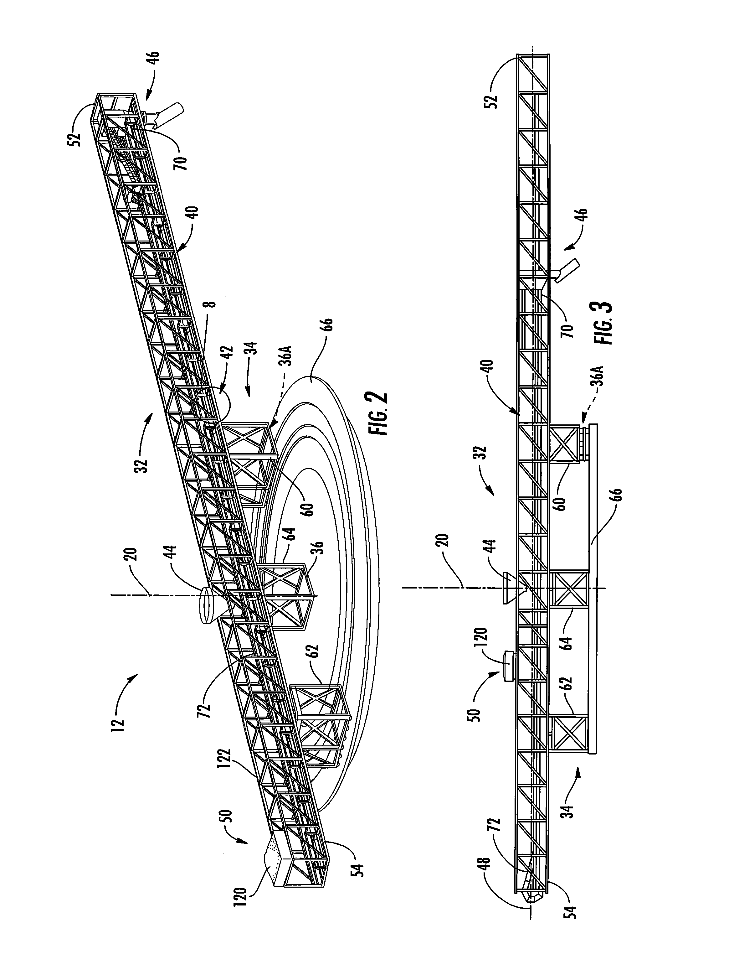
This patent describes an improved bulk material handling system that includes a first loading boom assembly and a supply bridge assembly. The first loading boom assembly has a horizontal boom frame and a vertical boom frame supporting it, with a boom frame rotation mechanism that allows the boom frames to rotate. The boom conveyor mechanism is attached to the boom frame and can slide along the boom axis in two directions. The system also includes a receiving hopper and a discharge spout for conveying bulk material. The supply bridge assembly has an elevated bridge frame with a first bridge discharge chute for discharging bulk material. The system can also include additional loading boom assemblies and bridge conveyor mechanisms for conveying bulk material. The technical effect of this patent is an improved and efficient system for handling bulk materials.

Problems solved by technology

The handling of bulk materials in such situations, and particularly at the rates and volumes demanded by modern industry, presents many challenges.
For example, when loading a ship or barge, it frequently necessary to move the vessel during the loading process in order to desirably distribute the bulk material at selected locations—which movements can result in an interruption of the loading process.
A separate, but related, problem is getting the bulk material from a common supply point to the equipment used for loading a particular ship or ships—which often involves transport over a considerable distance.

Method used


Image

  • Bulk material handling system and method
  • Bulk material handling system and method
  • Bulk material handling system and method

Examples


Embodiment Construction

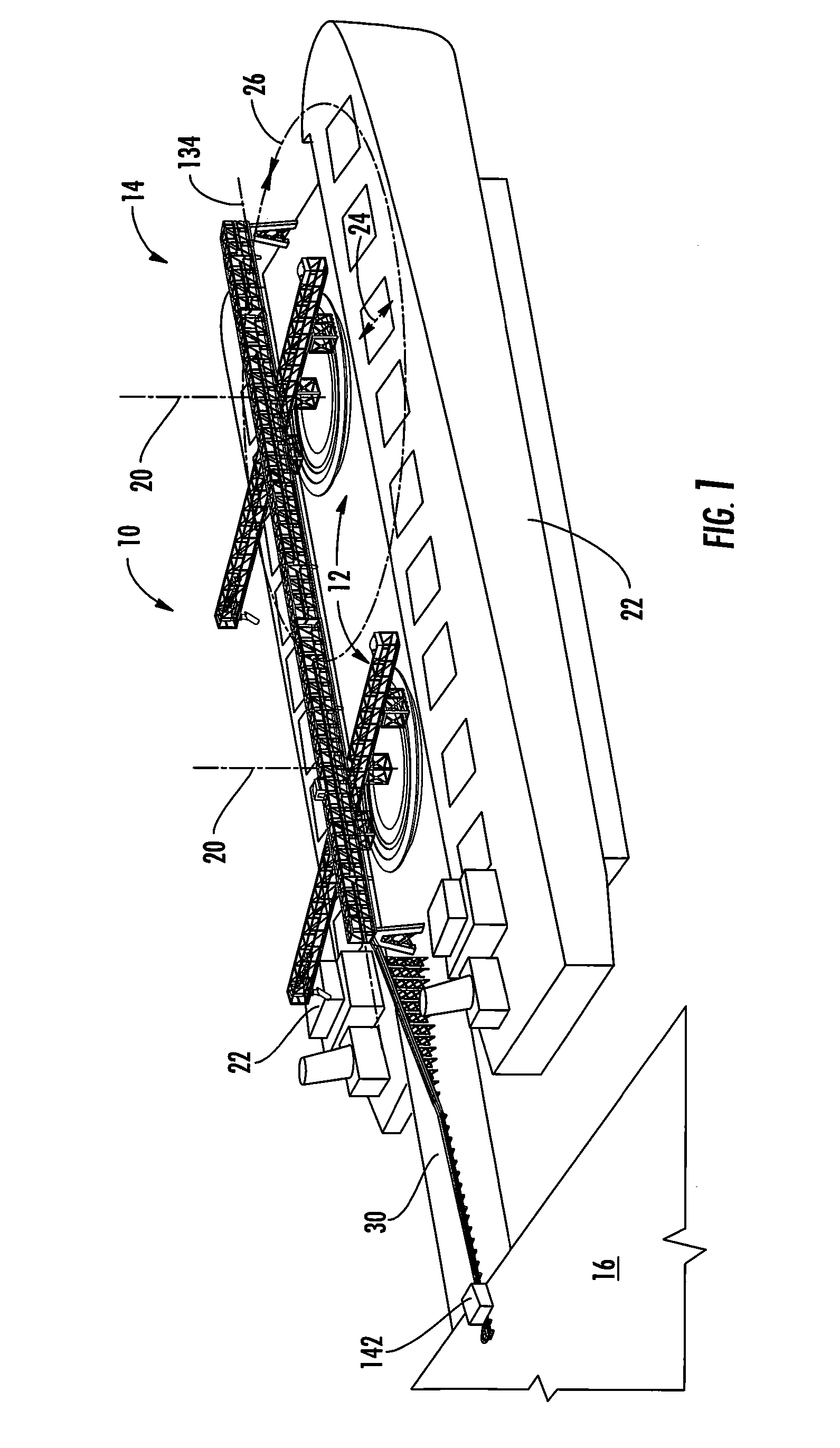
[0020]Referring to FIG. 1, according to an embodiment of the present invention, a bulk material handling system 10 includes a plurality of loading boom assemblies 12 and a loading boom supply bridge assembly 14. Via the loading boom supply bridge assembly 14 bulk materials are transported from a bulk material supply point 16 to the loading boom assemblies 12. The loading boom assemblies 12 receive the bulk materials along respective loading axes 20 and discharge the bulk materials to bulk material destinations 22. As will be explained in greater detail below, the loading boom assemblies 12 are operable to vary their discharge points relative to their loading axes 20—most preferably both radially (arrow 24) and angularly (arrow 26).

[0021]In the depicted embodiment, the bulk material destinations 22 are ships, such that the bulk material handling system 10 functions as an efficient and flexible ship loading system; however, it will be appreciated that the present invention could be ap...


PUM


Abstract

A bulk material handling system and method use a horizontal boom frame supporting a conveyor mechanism for bulk material that is slidable relative to the horizontal boom frame. The conveyor mechanism is positioned such that, with bulk material received at a fixed location, or loading axis, on the horizontal boom frame, a portion of the conveyor mechanism will always be positioned to receive bulk material. The horizontal boom frame can also be made rotatable about the loading axis. By rotating the horizontal boom frame and advancing or withdrawing the conveyor mechanism, the discharge point for bulk materials relative to the loading axis can be altered radially and angularly without interrupting the flow of bulk materials through the system. A supply bridge assembly can be employed to bring the bulk materials to the loading axis of the boom.

Description

CROSS-REFERENCE TO RELATED APPLICATIONS[0001]This application is a continuation of U.S. Non-Provisional patent application Ser. No. 13 / 849,820, filed on Mar. 25, 2013, which is a continuation-in-part of U.S. Non-Provisional patent application Ser. No. 13 / 571,239, filed on Aug. 9, 2012, which claims the benefit of U.S. Provisional Patent Application Ser. No. 61 / 521,559, filed on Aug. 9, 2011, the contents of which applications are herein incorporated by reference in their entirety.FIELD OF THE INVENTION[0002]The present invention relates to the handling of bulk materials, and more particularly, to the systems and methods for loading bulk materials from a supply point onto ships or other transports.BACKGROUND OF THE INVENTION[0003]Given that the majority of bulk materials are usually not generated where they are to be employed, it is necessary to load bulk materials onto various transports to take them to their ultimate locations for use. For example, coal, metal ore and the like will...

Claims


Application Information

Patent Timeline
Patent Type & Authority Applications(United States)
IPC IPC(8): B65G15/26B65G37/00B65G67/60
CPCB65G15/26B65G37/00B65G67/606B65G17/02
Inventor DIBBLE, MERTON F.
Owner RAIL VEYOR TECH GLOBAL
Learn More