
Vision Stimulator

a technology of stimulators and vision, applied in the field of vision stimulators, can solve the problems of limited vision field, individual brain to stop perceiving light, and create psychological problems for individuals,

Inactive Publication Date: 2015-06-18
GOTTLIEB DANIEL D
View PDF2 Cites 0 Cited by
  • Summary
  • Abstract
  • Description
  • Claims
  • Application Information

AI Technical Summary

Benefits of technology

The present invention is a handheld device that mimics the effect of moving a pen light. It consists of multiple lights arranged in a pattern that when turned on and off sequentially create a visual effect that simulates the movement of a single light across the pattern. The device also has the ability to control the speed and brightness of the sequential illumination. This invention is useful for treating individuals with visual attention disorders or cortical visual impairments. The method involves placing the device at the edge of the individual's field of vision loss and blinking the lights.

Problems solved by technology

This brain trauma may cause an individual's brain to stop perceiving light from an area of the field of vision, even though the individual's eyes are still physically capable of receiving light from the entire visual field.
The limited field of vision is not only dangerous, but can create psychological issues for the individual that interfere with recovery from the trauma.
The problem with shaking a pen light is that the motion is inconsistent and difficult to adjust to a speed and brightness that may be more beneficial to the patient.
Also, the process of shaking the pen light can often be uncomfortable for the physician or caregiver (the present inventor has developed carpal tunnel syndrome due, in part, to the practice of shaking a pen light for patients).
To date, no devices have been developed that effectively simulate this known light treatment therapy.

Method used


Image

  • Vision Stimulator
  • Vision Stimulator
  • Vision Stimulator

Examples


Embodiment Construction

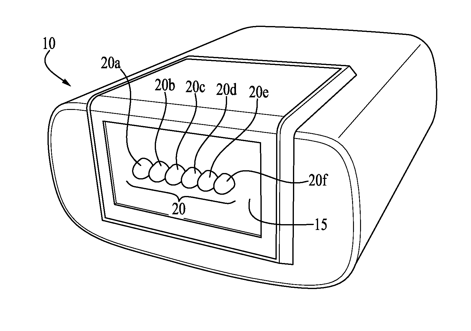
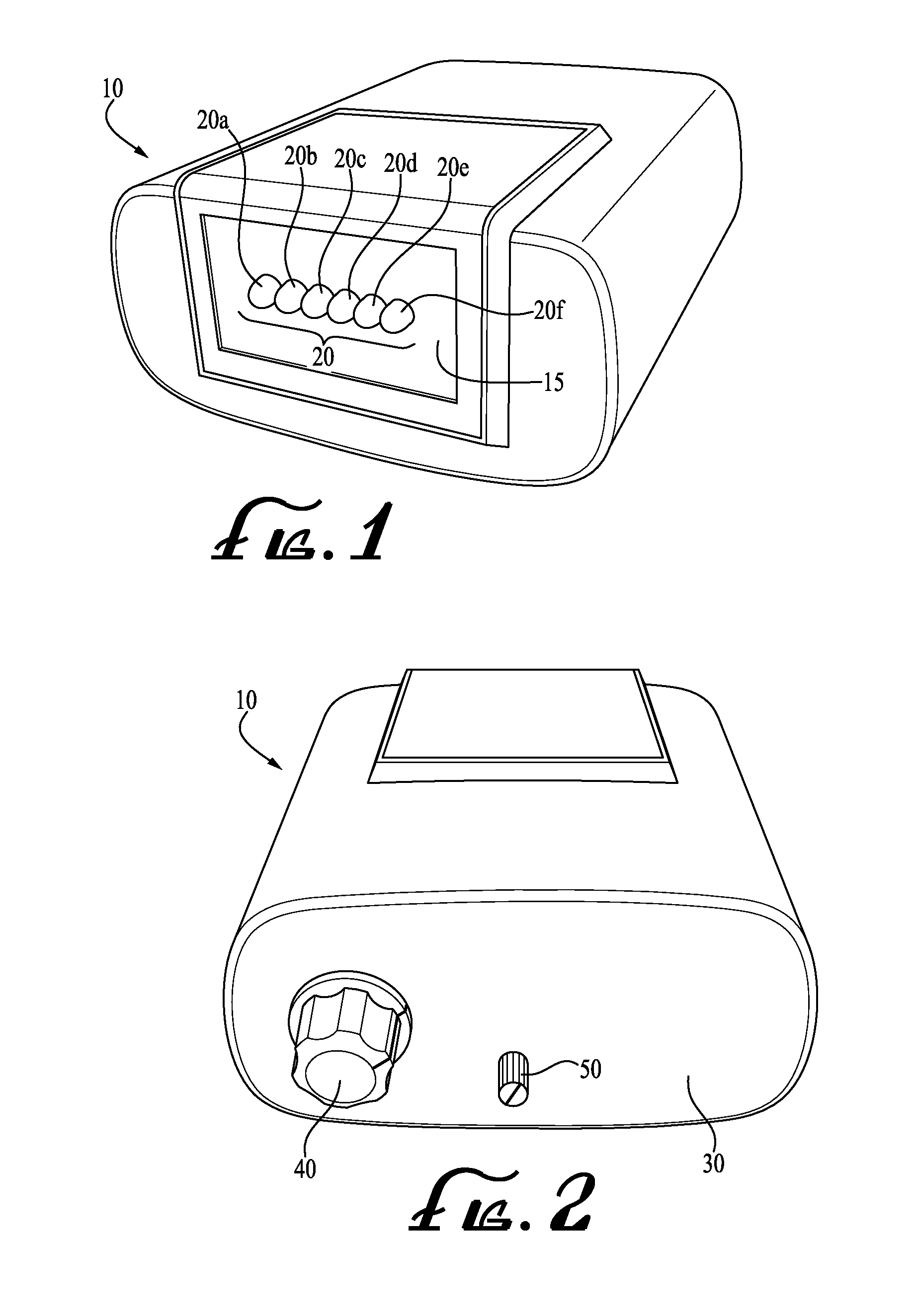
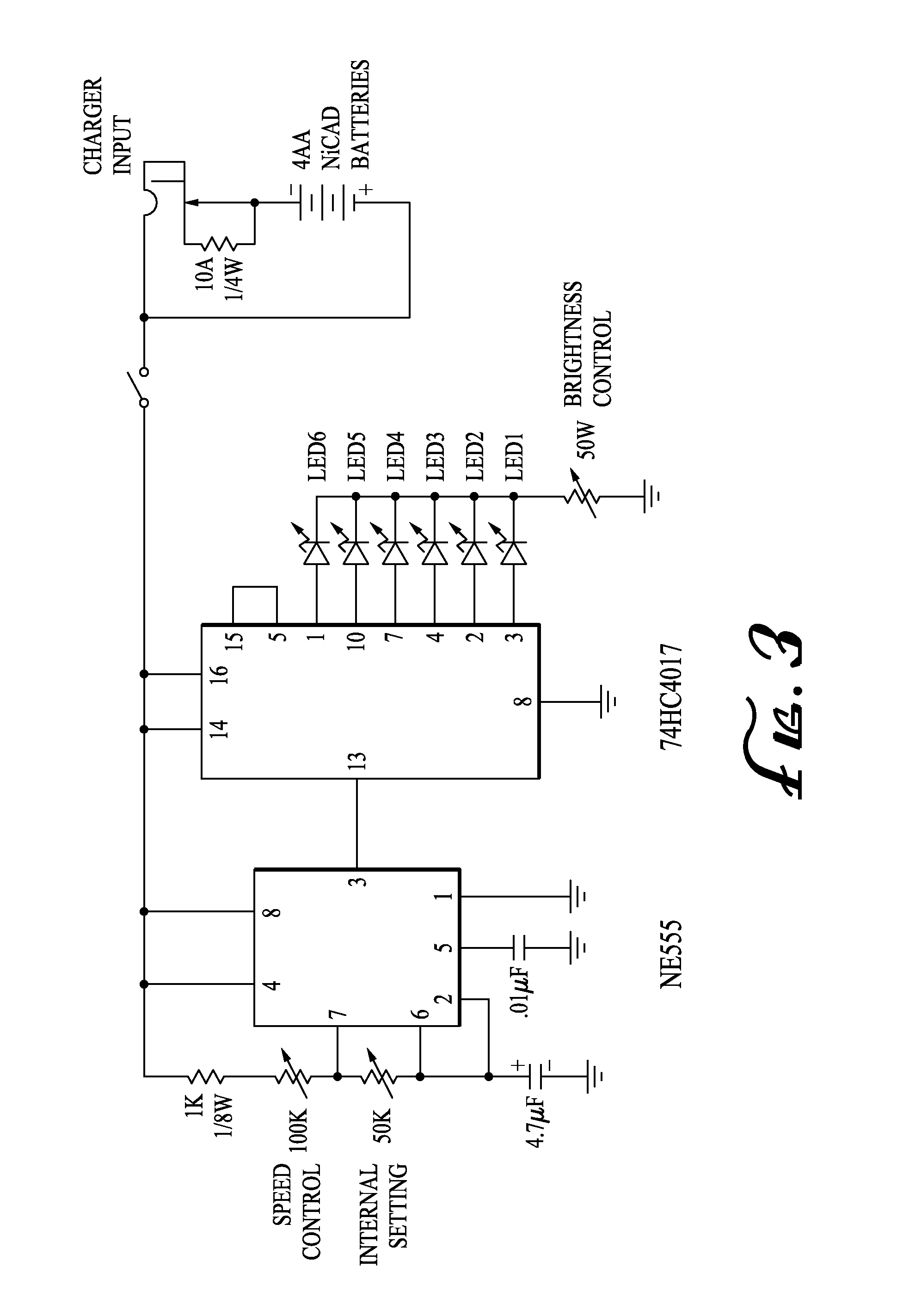
[0021]Accordingly, the present invention provides a device 10 that emits light in a manner that will simulate rapid movement of a single light, and assist in stimulating visual improvement within a perceived field of vision loss. To simulate movement, the present invention may utilize a series of lights 20a-20f arranged substantially linearly, or in another sequential pattern. Lights 20 may be designed to blink on and off sequentially so that a single point of light appears to be moving across the light series 20a-20f. The size and design of device 10 is virtually unlimited, but the size of the lights should be small enough to be placed along the boundary of the patient's field of vision loss. If the lights are too large, then the effect of motion may be lost, or the brain not be sufficiently stimulated to expand the vision field.

[0022]Turning now to FIG. 1, device 10 embodying the present invention is shown. Device 10 may comprise a front panel 15 having six (6) light emitting diod...


PUM


Abstract

A handheld device is disclosed for assisting in stimulating vision improvement in individuals with visual field loss caused by brain trauma or cortical visual impairment. The device comprises a number of lights arranged in a pattern, which blink sequentially to provide the visual effect of a single light moving across the pattern. The device may be set to create the visual motion effect, and then placed at the edge of the field of vision loss so that the individual's brain will sense movement within the visual field and track that movement into the blind spot. The device includes controls to adjust the brightness and frequency of the blinking lights.

Description

PRIORITY CLAIM[0001]This application claims the benefit of U.S. Provisional Patent Application No. 61 / 917,804 filed by this same inventor on Dec. 18, 2013.TECHNICAL FIELD[0002]The present invention relates generally to a device for assisting in stimulating vision improvement in individuals suffering from vision field loss, and, more specifically, to a device comprising a series of lights that blink sequentially to simulate movement and assist a patient's brain in expanding the perceived field of vision.BACKGROUND OF THE INVENTION[0003]Many people suffer from a loss of their normal field of vision, or hemianopia, created by some type of brain trauma such as an accident or stroke. This brain trauma may cause an individual's brain to stop perceiving light from an area of the field of vision, even though the individual's eyes are still physically capable of receiving light from the entire visual field. The limited field of vision is not only dangerous, but can create psychological issue...

Claims


Application Information

Patent Timeline
Patent Type & Authority Applications(United States)
IPC IPC(8): A61N5/06
CPCA61N5/0622A61N2005/0651A61N2005/0629A61N2005/0644A61N2005/0652
Inventor GOTTLIEB, DANIEL D.
Owner GOTTLIEB DANIEL D
Learn More