
Shifting manipulation apparatus for vehicle

Inactive Publication Date: 2015-06-18
HYUNDAI MOTOR CO LTD
View PDF3 Cites 5 Cited by
  • Summary
  • Abstract
  • Description
  • Claims
  • Application Information

AI Technical Summary

Benefits of technology

The present invention is about a shifting device for a vehicle that can smoothly and comfortably shift without locking in position. The device also helps reduce the shock experienced at the end of shifting, improving the overall shifting experience in the vehicle.

Problems solved by technology

However, the inertial body 508 fixed to the shift lever 502, as described above, is designed to apply a predetermined inertia force to the shift lever 502 regardless of the movement of the shift lever 502, so that there is a limit in improving the comfort in shifting and it causes a shifting shock and unsmooth operation due to excessive inertia at the end of shifting.

Method used


Image

  • Shifting manipulation apparatus for vehicle
  • Shifting manipulation apparatus for vehicle
  • Shifting manipulation apparatus for vehicle

Examples


Embodiment Construction

[0025]Reference will now be made in detail to various embodiments of the present invention(s), examples of which are illustrated in the accompanying drawings and described below. While the invention(s) will be described in conjunction with exemplary embodiments, it will be understood that the present description is not intended to limit the invention(s) to those exemplary embodiments. On the contrary, the invention(s) is / are intended to cover not only the exemplary embodiments, but also various alternatives, modifications, equivalents and other embodiments, which may be included within the spirit and scope of the invention as defined by the appended claims.

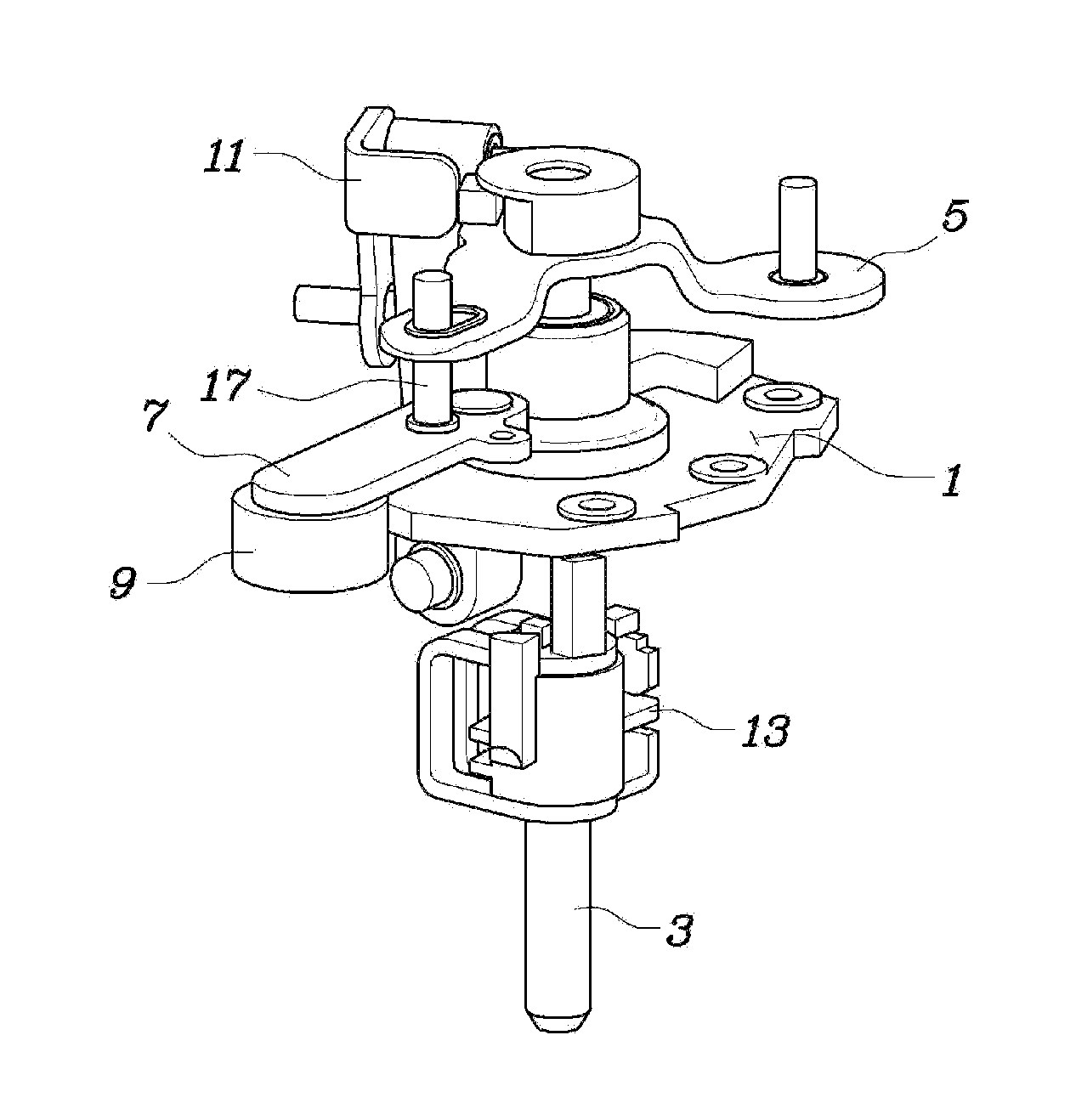
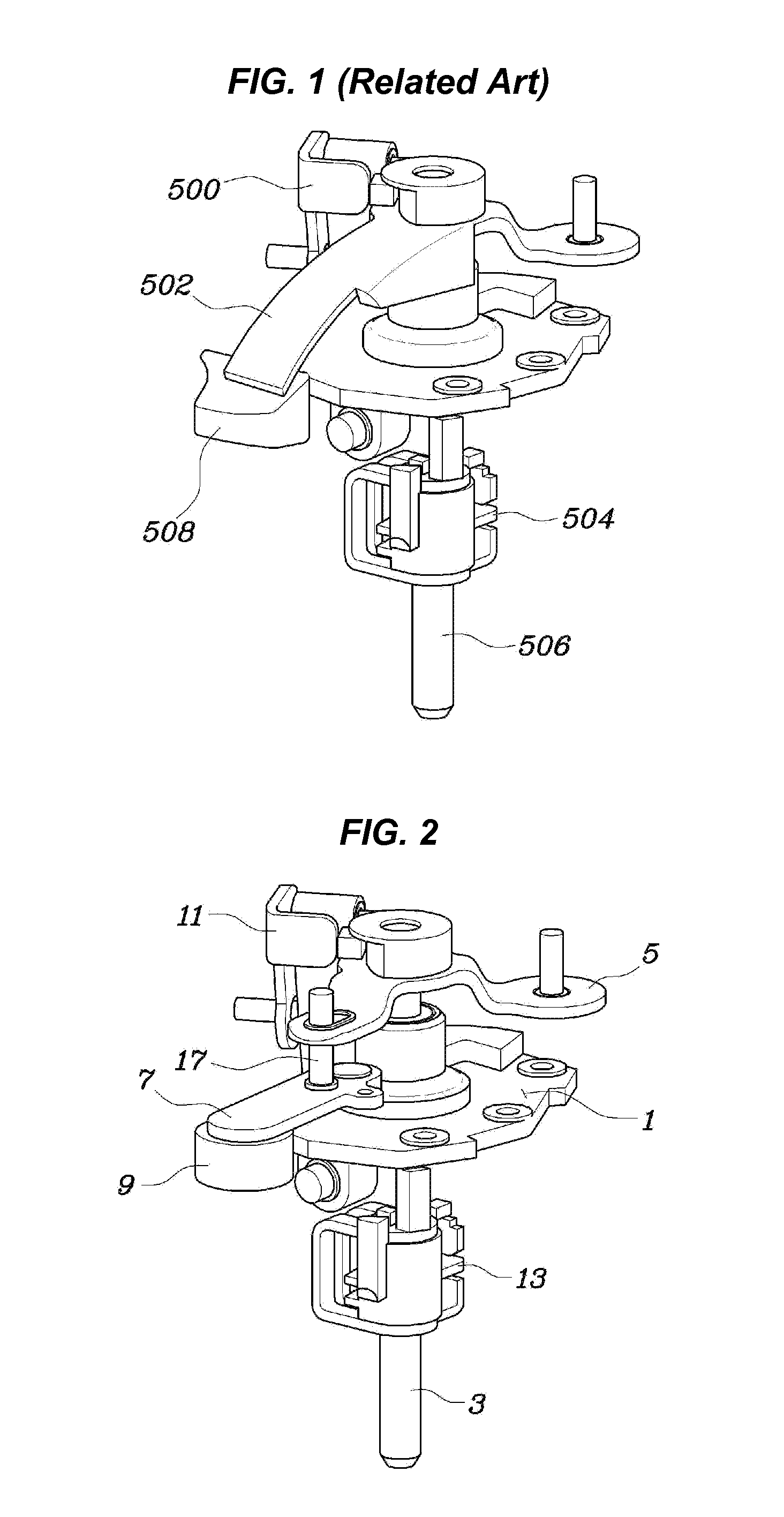
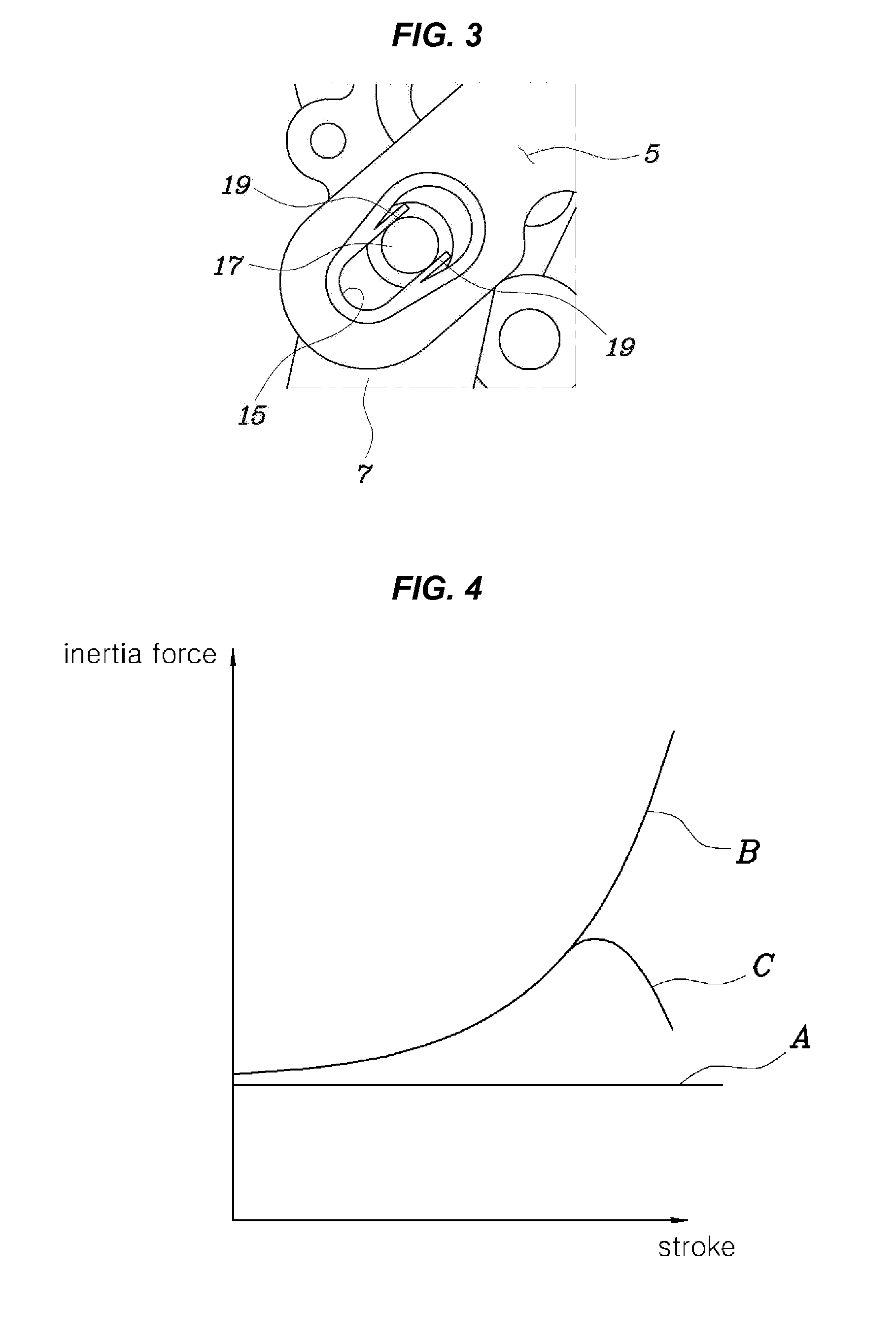
[0026]Referring to FIGS. 1 to 3, an exemplary embodiment of a shifting device for a vehicle according to an exemplary embodiment of the present invention includes, a control rod 3 disposed on a support 1 to be able to rotate and slide straight, a shift lever 5 mounted on the control rod 3 to rotate the control rod 3 about the supp...


PUM


Abstract

A shifting device for a vehicle may include a control rod disposed on a support and being configured to rotate and slide straight, a shift lever mounted on the control rod to rotate the control rod about the support by moving straight, a driven arm disposed on the support and rotatable about a rotation axis parallel to the control rod, an inertial body disposed at a free end of the driven arm, and an arm rotating mechanism engaging the shift lever and the driven arm to transmit a rotation of the shift lever to the driven arm.

Description

CROSS-REFERENCE TO RELATED APPLICATION[0001]The present application claims priority to Korean Patent Application No. 10-2013-0158743 filed on Dec. 18, 2013, the entire contents of which is incorporated herein for all purposes by this reference.BACKGROUND[0002]1. Field of the Invention[0003]The present invention relates to a shifting device for a vehicle, and more particularly to the structure of a shift lever of a manual transmission.[0004]2. Description of Related Art[0005]Manual transmissions shift to the gears that a driver wants by transmitting a force for operating a shifting lever applied by the driver to a select lever and a shift lever through a cable.[0006]FIG. 1 shows a portion of a shifting device of the related art, which includes a select lever 500 receiving a selecting force applied by a driver, a shift lever 502 receiving a shifting force, and a control rod 506 moved up / down in the figure by the selecting force and shifting to a shifting finger 504 by being rotated by...

Claims


Application Information

Patent Timeline
IPC IPC(8): F16H63/04F16H61/02
CPCF16H61/0293F16H63/04F16H63/30F16H2306/00F16H61/24F16H2061/246Y10T74/19251F16H63/00
Inventor SON, BONG GUY
Owner HYUNDAI MOTOR CO LTD
Features
  • Generate Ideas
  • Intellectual Property
  • Life Sciences
  • Materials
  • Tech Scout
  • Unparalleled Data Quality
  • Higher Quality Content
  • 60% Fewer Hallucinations
Learn More