Camera tampering protection

a technology for tampering protection and cameras, applied in camera filters, television systems, instruments, etc., can solve the problems of high risk of reflection in glass, compromise image quality, and compromise image quality, so as to improve tampering protection, reduce risk, and improve the effect of tampering protection

Active Publication Date: 2015-06-18
AXIS
View PDF7 Cites 43 Cited by
  • Summary
  • Abstract
  • Description
  • Claims
  • Application Information

AI Technical Summary

Benefits of technology

[0006]In view of the above, it is thus an object of the present invention to provide improved tampering protection for a monitoring camera. According to a first aspect of the invention a protective camera enclosure for a monitoring camera comprises a cover portion which is selectively moveable, in response to a detected tampering threat, from a retracted configuration exposing the camera to an extended configuration covering and physically protecting the camera. In this way the risk is greatly reduced for the camera to be damaged and the cost and labor of replacing or repairing willfully damaged cameras may be spared by protecting the camera fro

Problems solved by technology

Such a glass causes aberrations or distortions which compromises image quality.
Mounting the camera at a d

Method used


Image

  • Camera tampering protection
  • Camera tampering protection
  • Camera tampering protection

Examples


Embodiment Construction

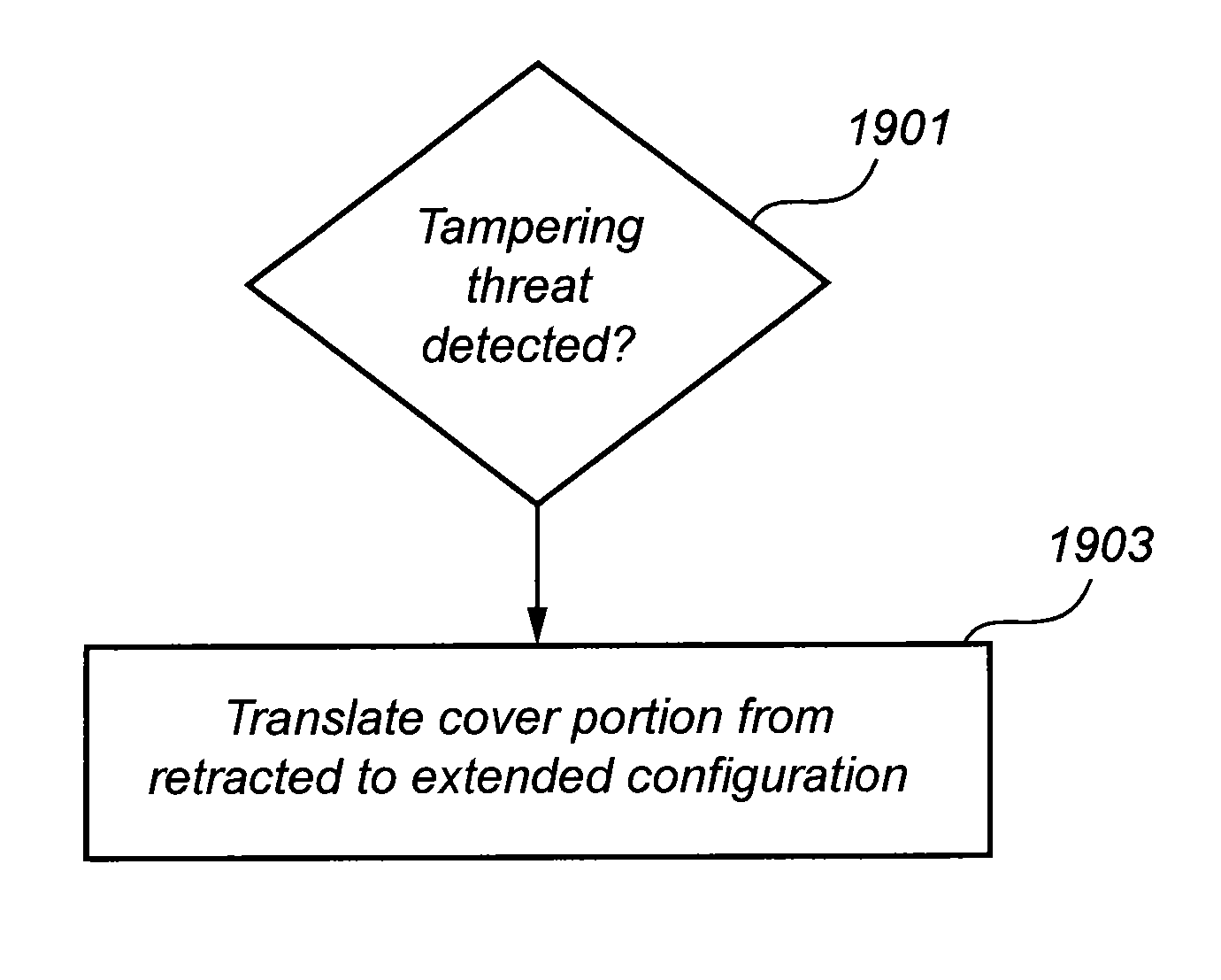
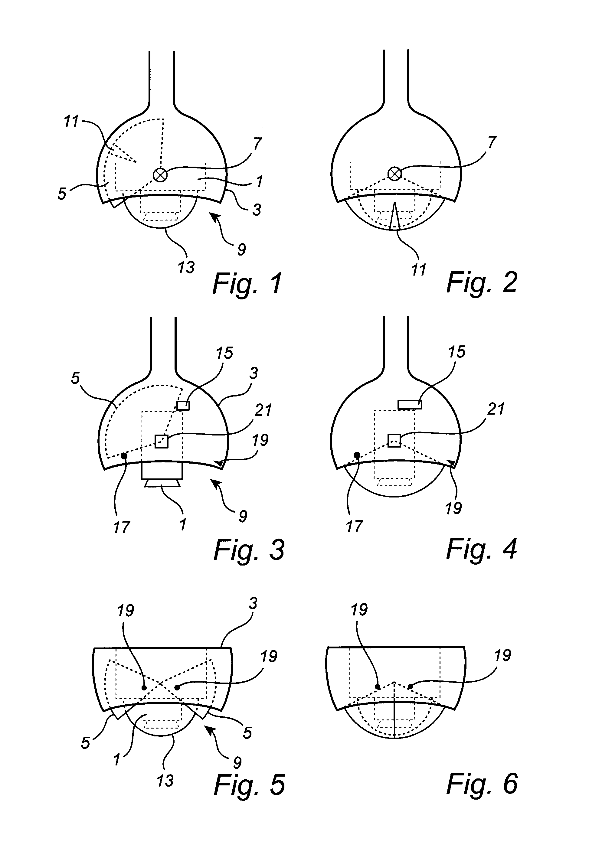
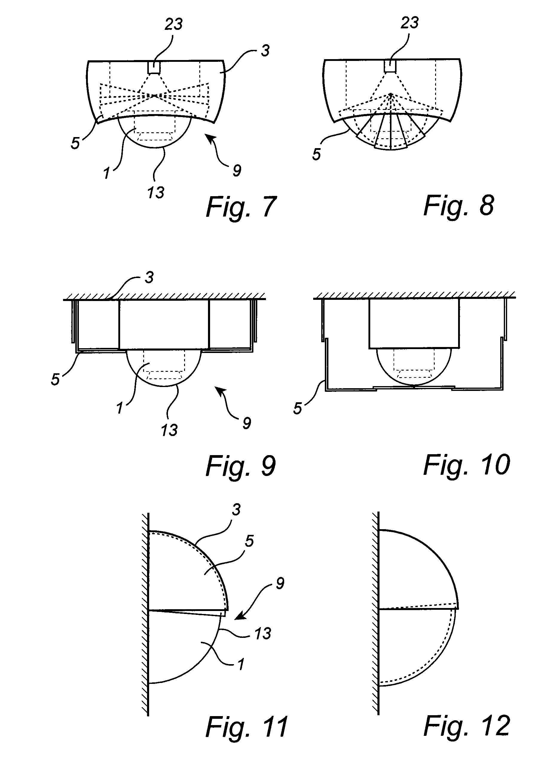
[0049]A monitoring camera 1 is mounted inside a protective camera enclosure 3 which is arranged to protect the camera against tampering attempts such as spraying of paint or external mechanical impact such as a hit from a baseball bat or similar, aimed at damaging the camera. The camera enclosure 3 includes a cover portion 5 which moves or translates from a retracted or open configuration or position to an extended or closed configuration or position, in response to a detected tampering threat, in order to protect the camera from tampering or sabotage.

[0050]The cover portion 5 shown in FIGS. 1-4 is in the form of a dome-shaped panel which can slide from a retracted configuration or position as shown in FIGS. 1 and 3 to an extended configuration or position as shown in FIGS. 2 and 4, by pivoting around an axis 7. In the extended configuration the cover portion covers a port or opening 9 in the camera enclosure 2, and in the retracted configuration the opening 9 is left open.

[0051]Whe...


PUM


Abstract

A protective camera enclosure (3) for a monitoring camera (1) comprises a cover portion (5) which is selectively moveable, in response to a detected tampering threat, from a retracted configuration exposing the camera (1) to an extended configuration covering and physically protecting the camera (1).

Description

TECHNICAL FIELD[0001]The present invention relates to a camera with tampering protection as well as a method for camera tampering protection.BACKGROUND[0002]Surveillance cameras are currently used in many different applications, for monitoring environments both indoors and outdoors. Cameras may e.g. be used for monitoring areas where there is a high risk of unwelcome activities such as burglary or vandalism. In such situations there is also a risk that the camera itself may be exposed to sabotage or tampering actions aimed to stop the camera from monitoring the area. Some examples of such actions are spraying paint on the camera lens, covering the camera view by a cloth or kicking or hitting the camera. When the view of a camera is obstructed or the camera is damaged, the images that are produced by the camera, if any, are obviously of limited use for surveillance purposes, and, thus, the unwelcome activities may go on unnoticed by an operator receiving images from the camera. Maint...

Claims


Application Information

Patent Timeline
IPC IPC(8): H04N5/225G06K9/46
CPCG06K9/46H04N5/2252G03B11/043G08B13/19619G08B29/046H04N23/51
Inventor LINDMAN, NIKLASHJELMSTROM, JONAS
Owner AXIS
Why Eureka
Try Eureka