Method for Controlling an Electric Lining Wear Compensator Device for a Disk Brake Arrangement and Disk Brake

Active Publication Date: 2015-06-25
KNORR-BREMSE SYST FUER NUTZFAHRZEUGE GMBH
View PDF5 Cites 6 Cited by
  • Summary
  • Abstract
  • Description
  • Claims
  • Application Information

AI Technical Summary

Benefits of technology

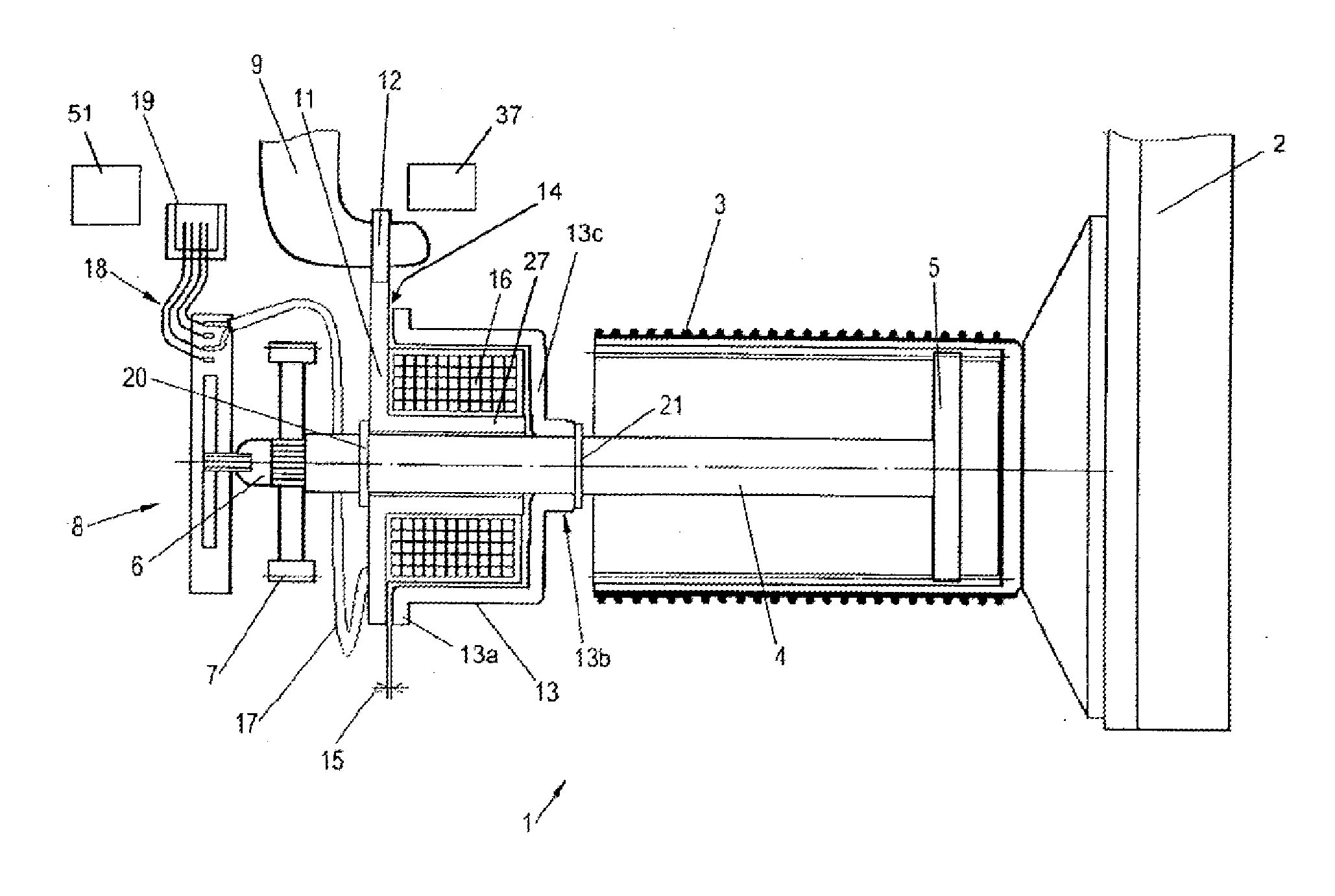
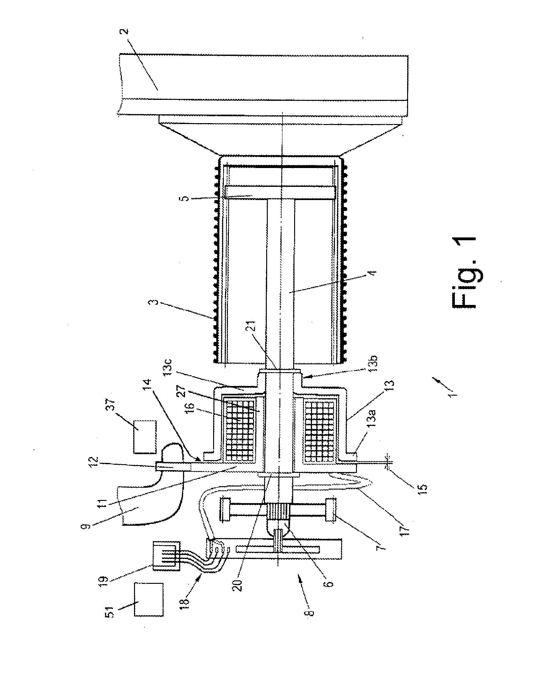
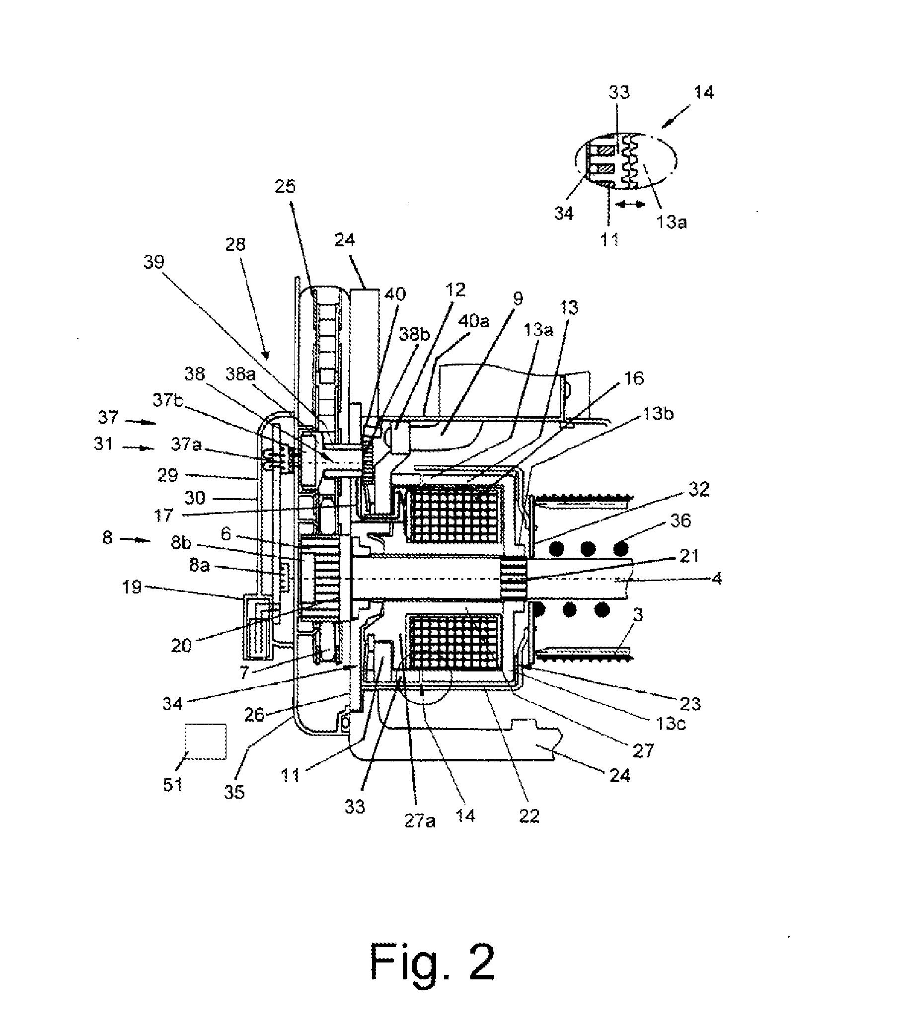
[0026]In one embodiment, the control device may be arranged on the electric pad wear readjustment device and thus form a so-called standalone version. In this way, retrofitting of existing series-produced disk brakes is possible because, for example, previous electromechanical potentiometers can be electronically reproduced, wherein terminals for potentiometers provided on a control unit can continue to be used by the reproduced terminals, for example by the contr

Problems solved by technology

However, microscopic mechanical movements and/or vibrations can impair a readjustment, that is to say a readjustment is for example performed incompletely, wherein an air clearance is to

Method used


Image

  • Method for Controlling an Electric Lining Wear Compensator Device for a Disk Brake Arrangement and Disk Brake
  • Method for Controlling an Electric Lining Wear Compensator Device for a Disk Brake Arrangement and Disk Brake
  • Method for Controlling an Electric Lining Wear Compensator Device for a Disk Brake Arrangement and Disk Brake

Examples


Example

[0097]FIG. 4 illustrates a schematic block circuit diagram of the second exemplary embodiment as per FIG. 3. By contrast to FIG. 3, this is not a standalone version. It is however self-evidently possible for each exemplary embodiment to be combined with each circuit, that is to say as per FIG. 3 or FIG. 4.

[0098]In the embodiment of FIG. 4, a so-called integrated solution is illustrated in which the evaluation circuit, that is to say the control device 51, is a constituent part of a controller 50, for example of a pressure regulating module and / or brake control unit. Therefore, no control device 51 is required on the printed circuit board 29 of the terminal device 28. The printed circuit board 29 is equipped with the connecting element 19, the plug connection 31, the pad wear sensor element 8a and the feed sensor element 37a. The terminal assignment of the connecting element 19 has a common ground (GND), the voltage supply +5V for the sensor elements 8a and 37a, the voltage supply (+...


PUM


Abstract

A method for controlling an electric pad wear compensator device of a disc brake arrangement, in particular for a motor vehicle, and a corresponding disk brake arrangement is provided. The disk brake arrangement includes control device that controls air clearance between a brake pad and a brake disk, a brake application device with a brake applicator lever coupled to the electric pad wear compensator device, and a readjustment spindle which receives at least a portion of the electric pad wear compensator device. The method for controlling the electric pad wear compensator device includes sensing the air clearance of the disc brake, comparing the detected air clearance with a preset value, and controlling the electric pad wear compensator device to adjust the air clearance to the preset value by energizing a solenoid of a coupling device of the electric pad wear compensator device during brake applicator lever movement.

Description

CROSS REFERENCE TO RELATED APPLICATIONS[0001]This application is a continuation of PCT International Application No. PCT / EP2013 / 065542, filed Jul. 23, 2013, which claims priority under 35 U.S.C. §119 from German Patent Application No. 10 2012 015 377.5, filed Aug. 3, 2012, the entire disclosures of which are herein expressly incorporated by reference.BACKGROUND AND SUMMARY OF THE INVENTION[0002]The invention relates to a method for controlling an electric pad wear readjustment device of a disk brake arrangement, in particular for a motor vehicle. The invention also relates to a corresponding disk brake arrangement and to a disk brake.[0003]Pad wear readjustment devices of said type are known in a variety of embodiments, such as for example mechanical readjusters with automatic adjustment of a friction point. In this case, the readjustment device is activated during every brake actuation, for example by way of a feed element of a brake-application device of the disk brake. In the eve...

Claims


Application Information

Patent Timeline
IPC IPC(8): F16D65/52F16D66/00
CPCF16D65/52F16D2065/386F16D66/00F16D55/2255F16D65/568
Inventor MILLER, BERNHARD
Owner KNORR-BREMSE SYST FUER NUTZFAHRZEUGE GMBH
Why Eureka
Try Eureka