Connecting mechanism for connection of the firearm receiver and the shoulder mount

a connection mechanism and firearm receiver technology, applied in the direction of weapons, butts, collapsible guns, etc., can solve the problems of inconvenient connection and disconnecting of the receiver and the shoulder mount, and the disadvantages of more modern designs, so as to achieve the effect of convenient latch control

Active Publication Date: 2015-06-25
TSESKA ZBROEVKA AS
View PDF14 Cites 16 Cited by
  • Summary
  • Abstract
  • Description
  • Claims
  • Application Information

AI Technical Summary

Benefits of technology

[0009]In one of convenient embodiments the elastic means acts upon the latch to move it in the shooting direction and when the shoulder mount is removed or folded, the lever can be moved to put the latch in the unlocking position against the action of the elastic means while if the shoulder mount is in the shooting position, the shoulder mounts prevents the above mentioned lever movement and thus the movement of the latch to the unlocking position. It is also convenient if the closing part of the firearm receiver contains a pin for rotary connection to the folding shoulder mount, the elastic means is a compression spring, the lever can rotate around the pin while its top end is designed for manual control of the lever and its bottom end is connected to the latch while when the shoulder mount is removed or folded, the latch can be moved against the compression spring into the unlocking position by pushing of the top end of the lever in the shooting direction and when the shoulder mount is in the shooting position, the front face of the shoulder mount prevents the latch from moving into the unlocking position, which prevents unwanted separation of the shoulder mount from the receiver.
[0010]As indicated above, the mentioned disadvantage of problematic protection from unwanted pressing of the dismounting button under impact stress of the firearm, especially in the case of folding shoulder mounts is solved through spring-loading of the latch of the closing part of the receiver (hereinafter also the “latch” only) in the shooting direction and its securing by the base of the shoulder mount, which in the raised condition prevents compression of the latch and release of the connection of the closing part of the receiver and the firearm receiver. Thus, the connection is mechanically secured and to remove the closing part of the receiver the shoulder mount needs to be folded first.
[0011]To achieve easier control of the latch the compression mechanism can be conveniently fitted with a “lever of the closing part latch” (hereinafter also the “lever”) that can be rotated around the transversal axis. At one end the lever is arranged in such a way to have a compression area while its other end leans against the latch or is connected to it. By compression of the control area its other end in the connection or the contact point with the latch acts upon the latch and moves it against the shooting direction. On complete retraction of the latch the closing part can be slid out of the firearm receiver.
[0012]What should be mentioned about the shoulder mount is that it is preferentially a folding shoulder mount that can be simple as well as telescopic. However, the shoulder mount does not necessarily be folding, it may be any suitable shoulder mount that can be dismounted or separated from the closing part of the firearm receiver if necessary. This disassembly or separating of the shoulder mount from the closing part makes it possible to move the latch from the locking position, in which the latch fits behind the interface that the rear end of the receiver is equipped with, to the unlocking position, in which the closing part can be slid out of the receiver. On the other hand, if the shoulder mount is in the shooting position, the latch cannot be moved, so unwanted (spontaneous) releasing of the closing part from the firearm receiver is prevented.

Problems solved by technology

A consequence of these designs is quite inconvenient connecting and disconnecting of the receiver and the shoulder mount.
This means that these more modern designs also manifest some disadvantages.

Method used


Image

  • Connecting mechanism for connection of the firearm receiver and the shoulder mount
  • Connecting mechanism for connection of the firearm receiver and the shoulder mount
  • Connecting mechanism for connection of the firearm receiver and the shoulder mount

Examples


Embodiment Construction

OF EMBODIMENTS OF THE INVENTION

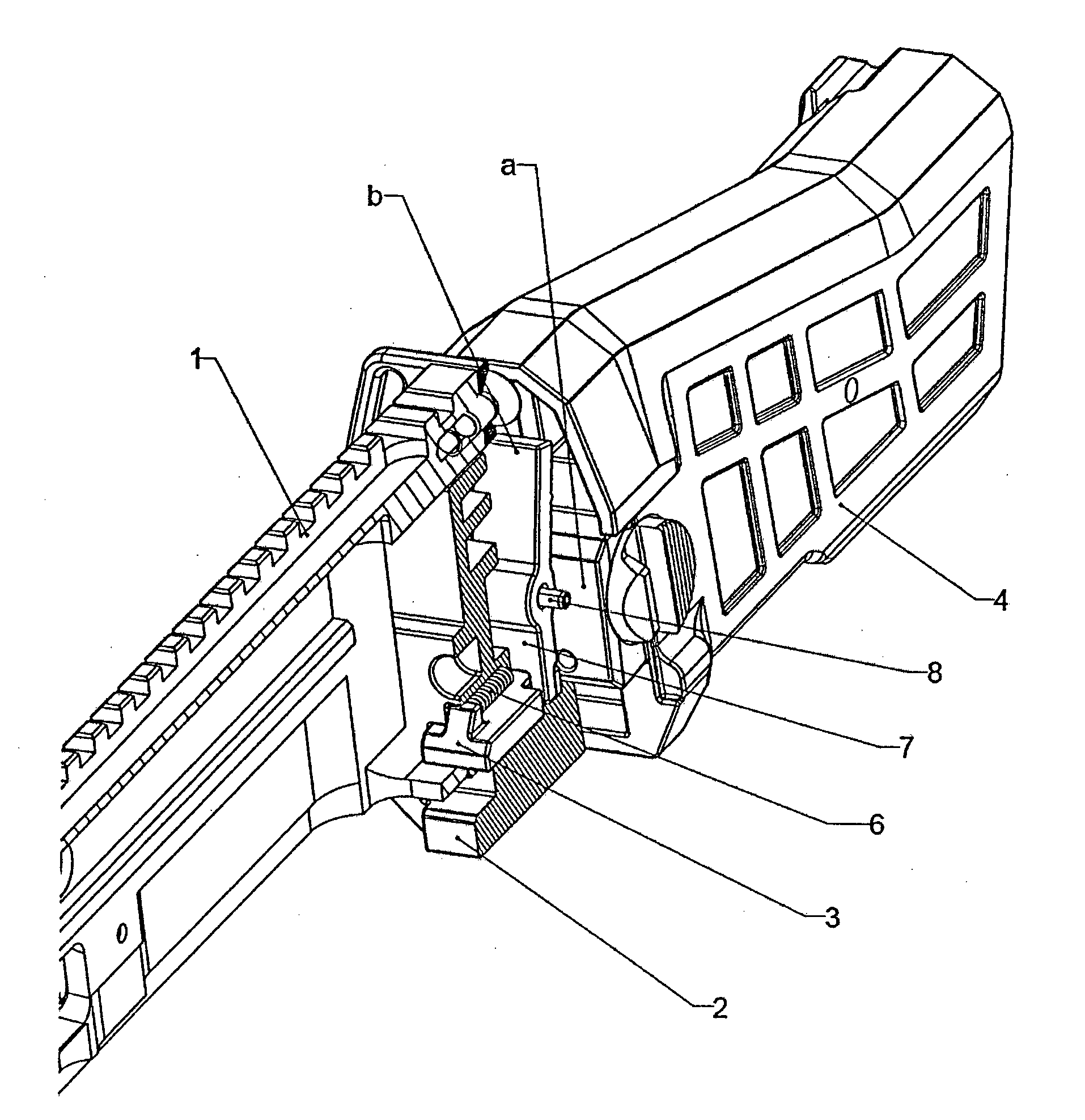
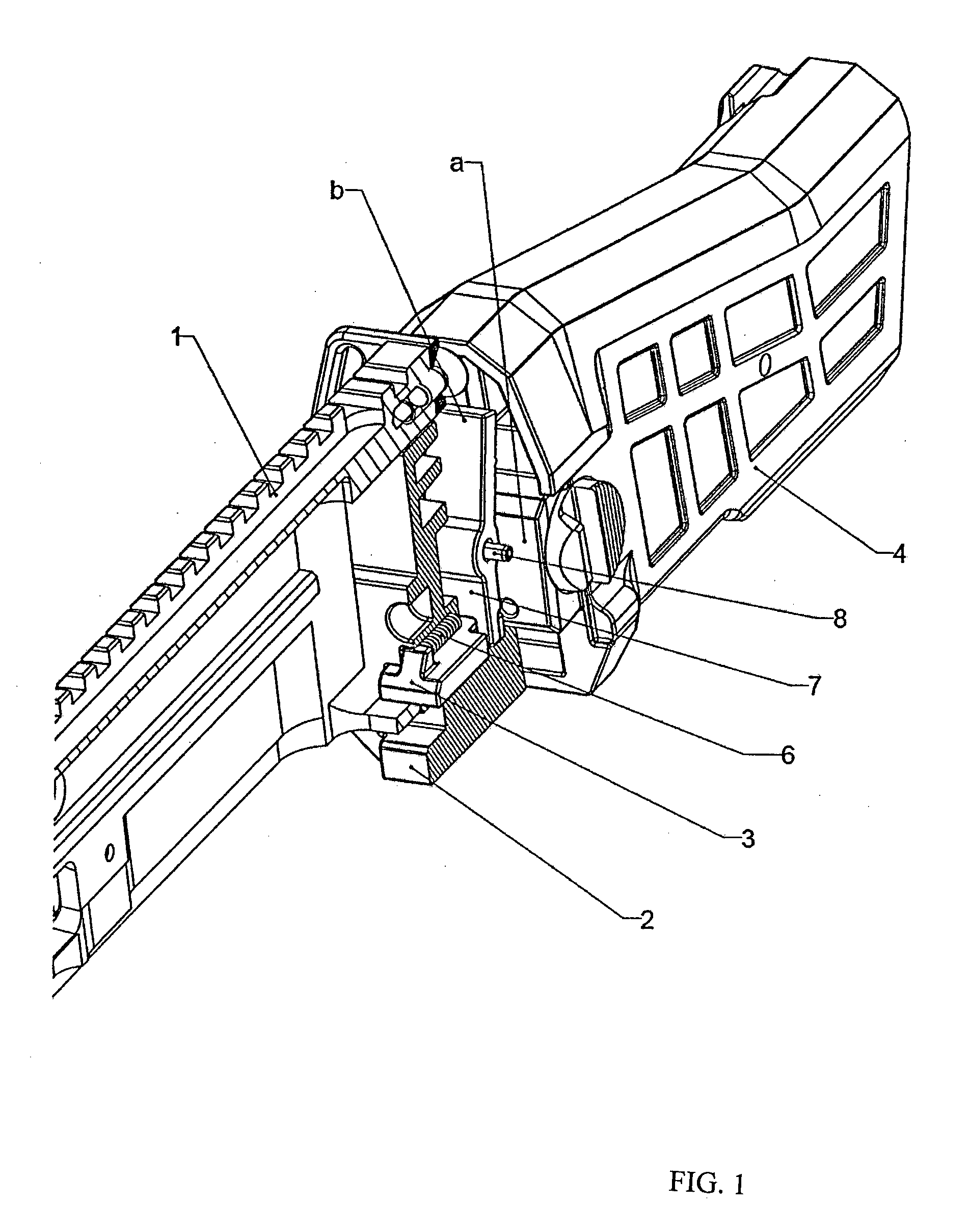
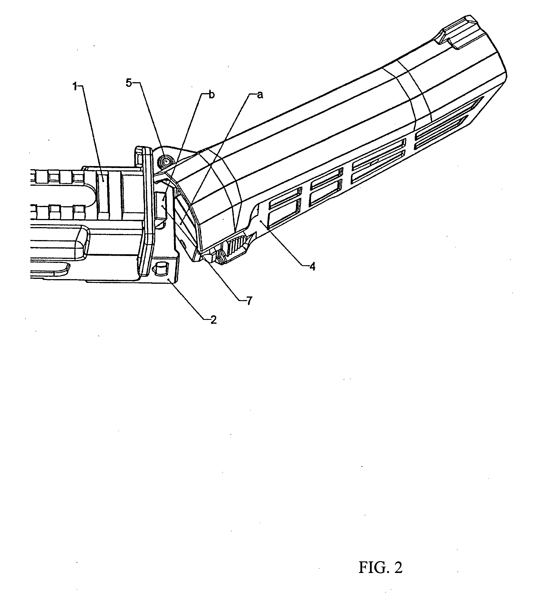
[0019]As shown in the attached drawings, the receiver 1 of the firearm is connected to the closing part 2 of the receiver 1 with the latch 3 of the closing part 2 of the receiver 1, which fits behind the fixed part of the receiver 1. The shoulder mount 4 can be rotated around the pin 5 located in the closing part 2 of the receiver 1. A spring 6 acts upon the latch 3 in the shooting direction. Complete extension of the latch 3 is prevented by securing of the latch by the latch lever 7, the lever being able to rotate around the pin 8. In a situation when the shoulder mount 4 is in the shooting position, i.e. is not folded away from the receiver 1, the front face a of the shoulder mount 4 prevents the latch 3 from being pushed against the shooting direction, i.e. to the unlocking position.

[0020]After folding the shoulder mount 4 away the top end b of the lever 7 of the latch 3 can be pushed in the shooting direction, the movement of the lever 7 being tran...


PUM


Abstract

A connection mechanism for connection of a firearm receiver and a shoulder mount, the fire arm receiver comprising a closing part, the closing part containing a latch arranged in a movable way between a locking position, in which in an assembled firearm the latch engages with the receiver and the closing part is prevented from being removed from the receiver, and an unlocking position, in which the latch disengages from the receiver and the closing part can be removed from the receiver. The closing part further contains a lever to control the movement of the latch from the locking position to the unlocking position and/or from the unlocking position to the locking position

Description

FIELD OF THE INVENTION[0001]The invention deals with a connection mechanism for connection of the firearm receiver and the shoulder mount.STATE OF THE ART[0002]In existing firearms dismountable pins of various designs are generally used to secure the connection of the receiver and the shoulder mount. A consequence of these designs is quite inconvenient connecting and disconnecting of the receiver and the shoulder mount. In some other designs the shoulder mount is firmly connected to the body of the trigger mechanism.[0003]In more up-to-date designs a dismounting button that connects the shoulder mount and the closing part of the receiver is used to secure the connection; a spring then acts upon the dismounting button against the shooting direction. What is important in these designs is securing the dismounting button in the firearm to prevent spontaneous unlocking of the connection under impact stress of the firearm, which is problematic with regard to the direction of unlocking of ...

Claims


Application Information

Patent Timeline
Patent Type & Authority Applications(United States)
IPC IPC(8): F41C23/14
CPCF41C23/14F41A3/64F41A3/66F41A11/04F41C23/04F41C23/20
Inventor SIMEK, VLADIMIR
Owner TSESKA ZBROEVKA AS
Why Eureka
Try Eureka