Check patentability & draft patents in minutes with Patsnap Eureka AI!

Method for point on wave switching and a controller therefor

a point on wave controller and controller technology, applied in the direction of electric switches, relays, electric apparatus, etc., can solve the problems of low accuracy of the point on wave controller present complicated procedural handling of the point on wave controller on the transfer bay, and stress in the circuit breaker as well as the connected power system components

Active Publication Date: 2015-06-25
HITACHI ENERGY SWITZERLAND AG
View PDF10 Cites 8 Cited by
  • Summary
  • Abstract
  • Description
  • Claims
  • Application Information

AI Technical Summary

Benefits of technology

The patent text describes a method for switching a subsystem in a multiphase electrical system using a first and second circuit breaker. The second controller receives system characteristics data from the first controller or a central repository and estimates the time for switching based on the data and the operating time of the second circuit breaker. The second controller then operates the second circuit breaker at the estimated time for switching to switch the subsystem. The technical effect of this method is to enhance the reliability and efficiency of the switching process in multiphase electrical systems, reducing downtime and improving overall operational performance.

Problems solved by technology

During this process, active elements of the circuit breaker either interrupt or incept high current, causing stresses in the circuit breaker as well as connected power system components.
However, currently the accuracy of the point on wave controller present on the transfer bay is lower than those of the point on wave controllers connected to the bays.
Additionally, point on wave switching on the transfer bay can be procedurally complex.
Therefore, when a load is transferred to the transfer bay, often improper switching operation occurs causing a reduction in life expectancy of the circuit breaker.

Method used


Image

  • Method for point on wave switching and a controller therefor
  • Method for point on wave switching and a controller therefor
  • Method for point on wave switching and a controller therefor

Examples


Embodiment Construction

[0014]The above-mentioned issues can be addressed by exemplary embodiments disclosed herein, as will be understood by reading the following specification.

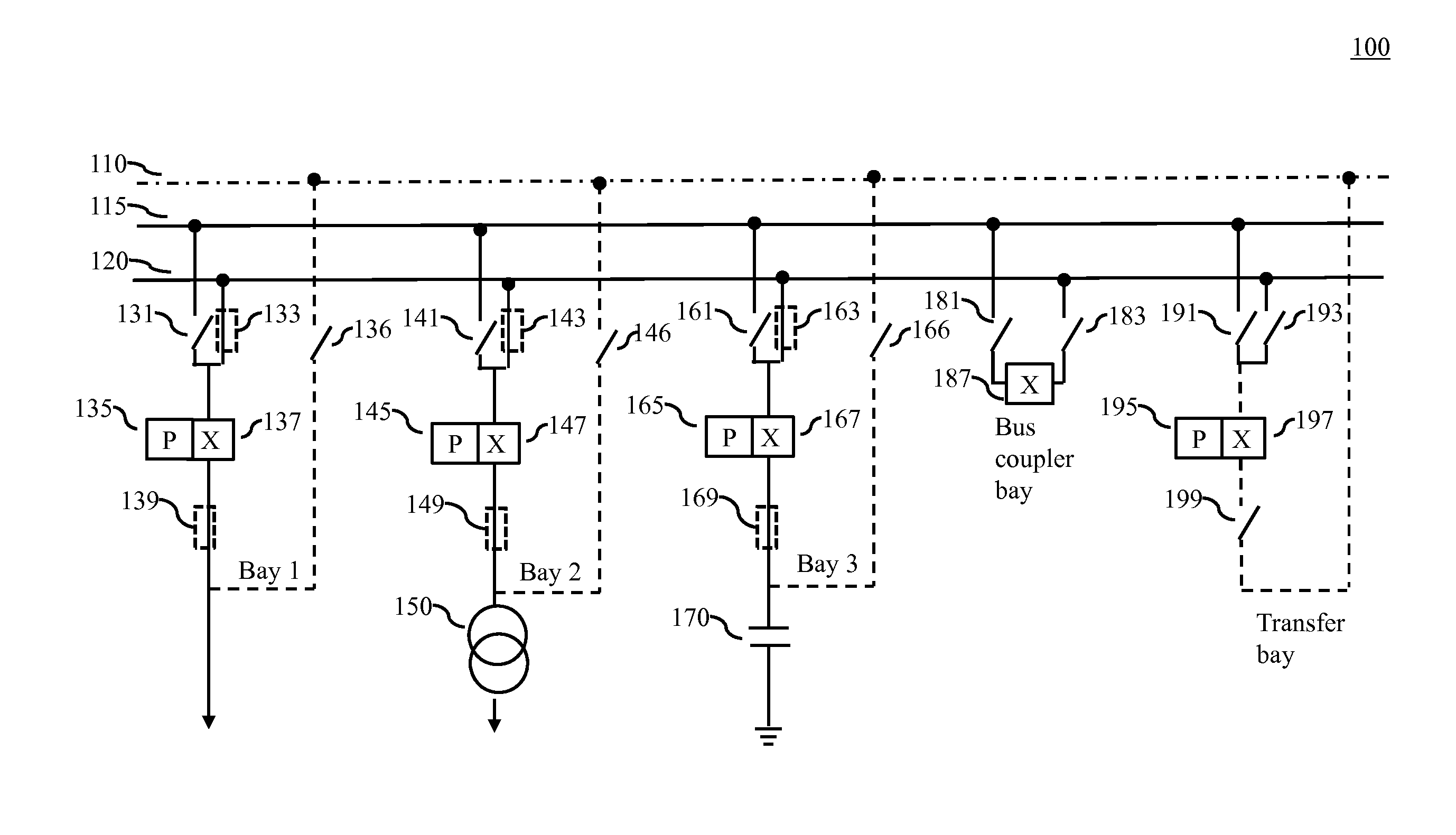
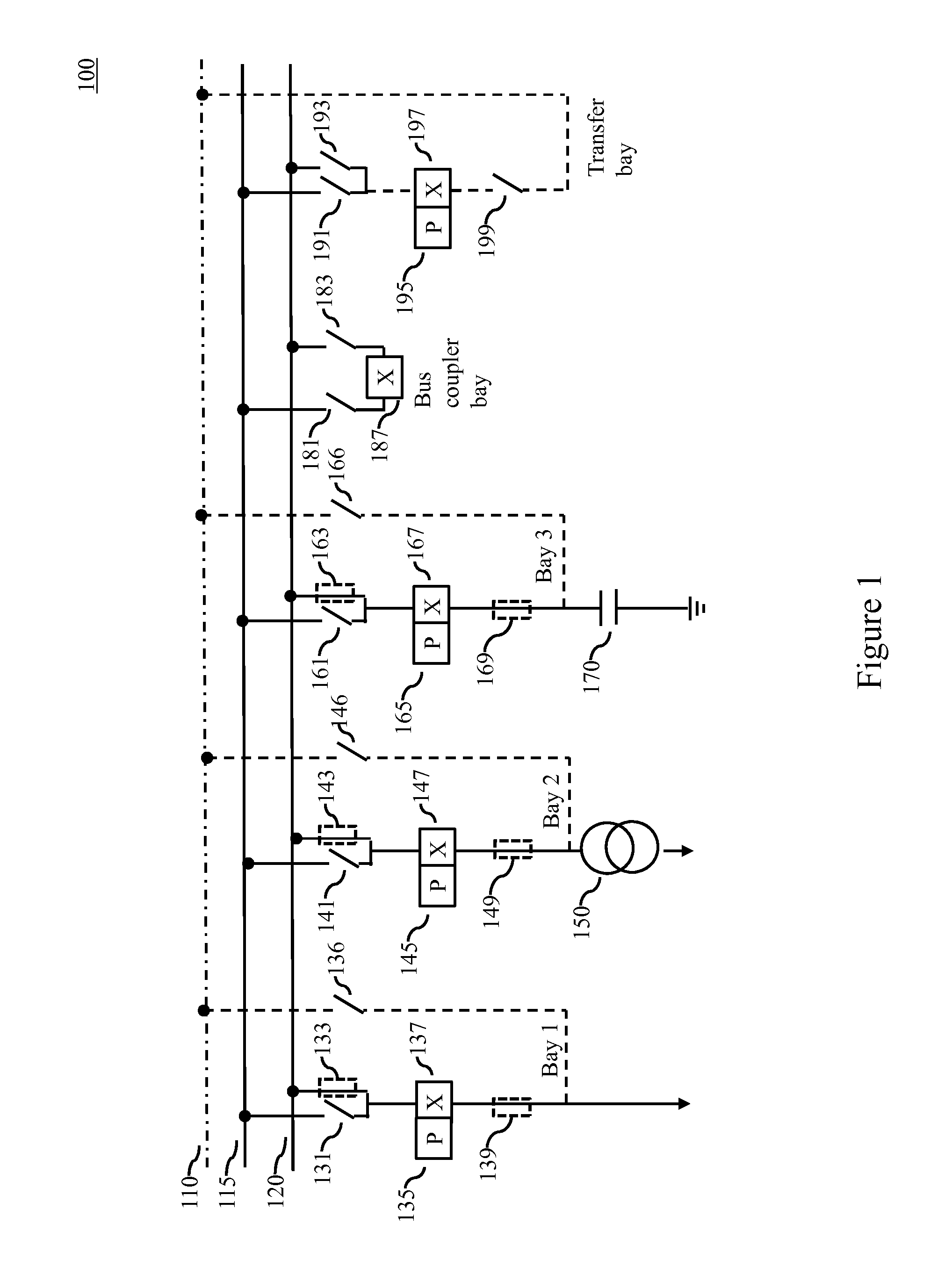
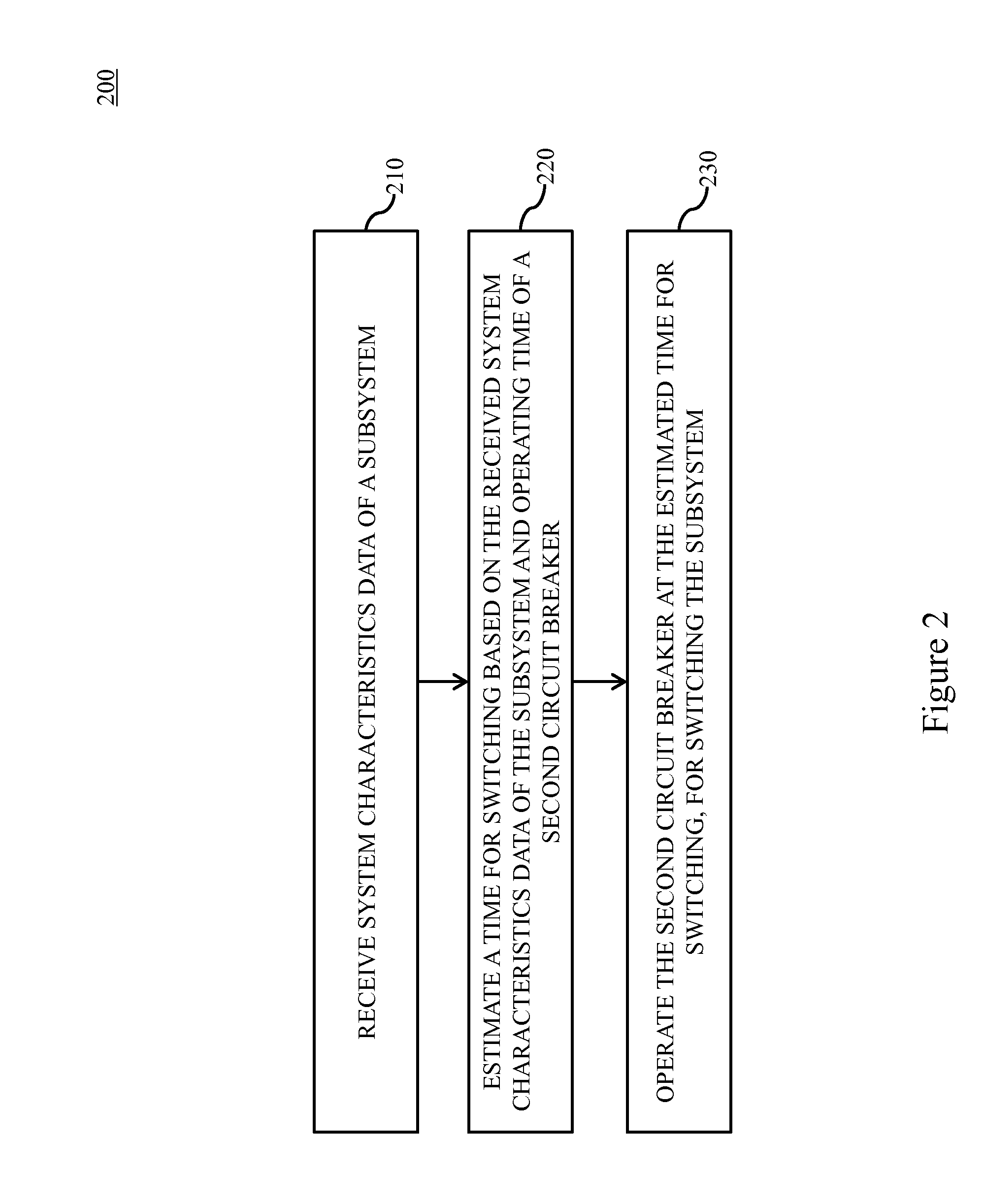
[0015]In one aspect, the present disclosure provides a method of performing point on wave switching in a multiphase electrical system having a first circuit breaker connected to a first bus, the first circuit breaker operated by a first controller, a second circuit breaker connected to a second bus, the second circuit breaker operated by a second controller, and a subsystem transferred from the first bus to the second bus. An exemplary method can include receiving by the second controller, system characteristics data of the subsystem, estimating by the second controller, a time for switching based on the received system characteristics data of the subsystem and operating time of the second circuit breaker, and operating by the second controller the second circuit breaker at the estimated time for switching, for switching the subsys...


PUM


Abstract

A method is disclosed of performing point on wave switching in a multiphase electrical system having a first circuit breaker connected a first bus, the first circuit breaker being operated by a first controller, a second circuit breaker connected to a second bus, the second circuit breaker being operated by a second controller, and a subsystem transferred from the first bus to the second bus. The method can include receiving, by the second controller, system characteristics data of the subsystem, estimating, by the second controller, a time for switching based on the received system characteristics data of the subsystem and operating time of the second circuit breaker, and operating, by the second controller, the second circuit breaker at the estimated time for switching, for switching the subsystem.

Description

RELATED APPLICATION[0001]This application claims priority under 35 U.S.C. §119 to Indian Patent Application No. 6040 / CHE / 2013 filed in India on Dec. 23, 2013, the entire content of which is hereby incorporated by reference in its entirety.FIELD[0002]The present disclosure relates to point on wave controllers. For example, the present disclosure relates to point on wave controllers employed on transfer bays.BACKGROUND INFORMATION[0003]In power systems, circuit breakers are used for connecting and disconnecting a load. During this process, active elements of the circuit breaker either interrupt or incept high current, causing stresses in the circuit breaker as well as connected power system components. The flow of the high current can be limited by closing and opening the circuit breaker at a specific instance on a source voltage waveform. A plurality of techniques are known for controlling the opening or closing of the circuit breaker in order to prevent generation of a transient phe...

Claims


Application Information

Patent Timeline
Patent Type & Authority Applications(United States)
IPC IPC(8): H01H9/56
CPCH01H9/56H01H71/123
Inventor PARAPURATH, ANOOPTALLURI, ANIL
Owner HITACHI ENERGY SWITZERLAND AG
Features
  • R&D
  • Intellectual Property
  • Life Sciences
  • Materials
  • Tech Scout
  • Unparalleled Data Quality
  • Higher Quality Content
  • 60% Fewer Hallucinations
Learn More