Zoom lens and imaging apparatus

a zoom lens and imaging apparatus technology, applied in the field of zoom lenses and imaging apparatuses, can solve the problems of difficult to excellently correct various aberrations through the entire variable magnification range, large optical system size, etc., and achieve excellent correction, and high variable magnification ratio

Inactive Publication Date: 2015-07-02
FUJIFILM CORP
View PDF1 Cites 2 Cited by
  • Summary
  • Abstract
  • Description
  • Claims
  • Application Information

AI Technical Summary

Benefits of technology

[0045]A zoom lens of the present invention consists of a first lens group having positive refractive power, a second lens group having negative refractive power, a third lens group having positive refractive power, a fourth lens group having negative refractive power, and a fifth lens group having positive refractive power in this order from an object side. The third lens group includes a cemented lens closest to the object side and a cemented lens closest to an image side, and the fourth lens group consists of a negative lens and a positive lens in this order from the object side. Further, distances between the lens groups change, and the fifth lens group is fixed, and at least the first lens group and the fourth lens group move when magnification is changed from the wide angle end to the telephoto end. Therefore, it is possible to provide the zoom lens in small size in which various aberrations are excellently corrected through an entire variable magnification range while the zoom lens has a high variable magnification ratio.
[0046]Further, the imaging apparatus of the present invention includes the zoom lens of the present invention. Therefore, it is possible to obtain high-image-quality video images at high variable magnification ratios, and to reduce the size of the apparatus.

Problems solved by technology

However, when a zoom lens having an even higher variable magnification ratio is tried to be achieved, there are problems that the size of an optical system tends to become large, and that it becomes difficult to excellently correct various aberrations through an entire variable magnification range.

Method used


Image

  • Zoom lens and imaging apparatus
  • Zoom lens and imaging apparatus
  • Zoom lens and imaging apparatus

Examples


Embodiment Construction
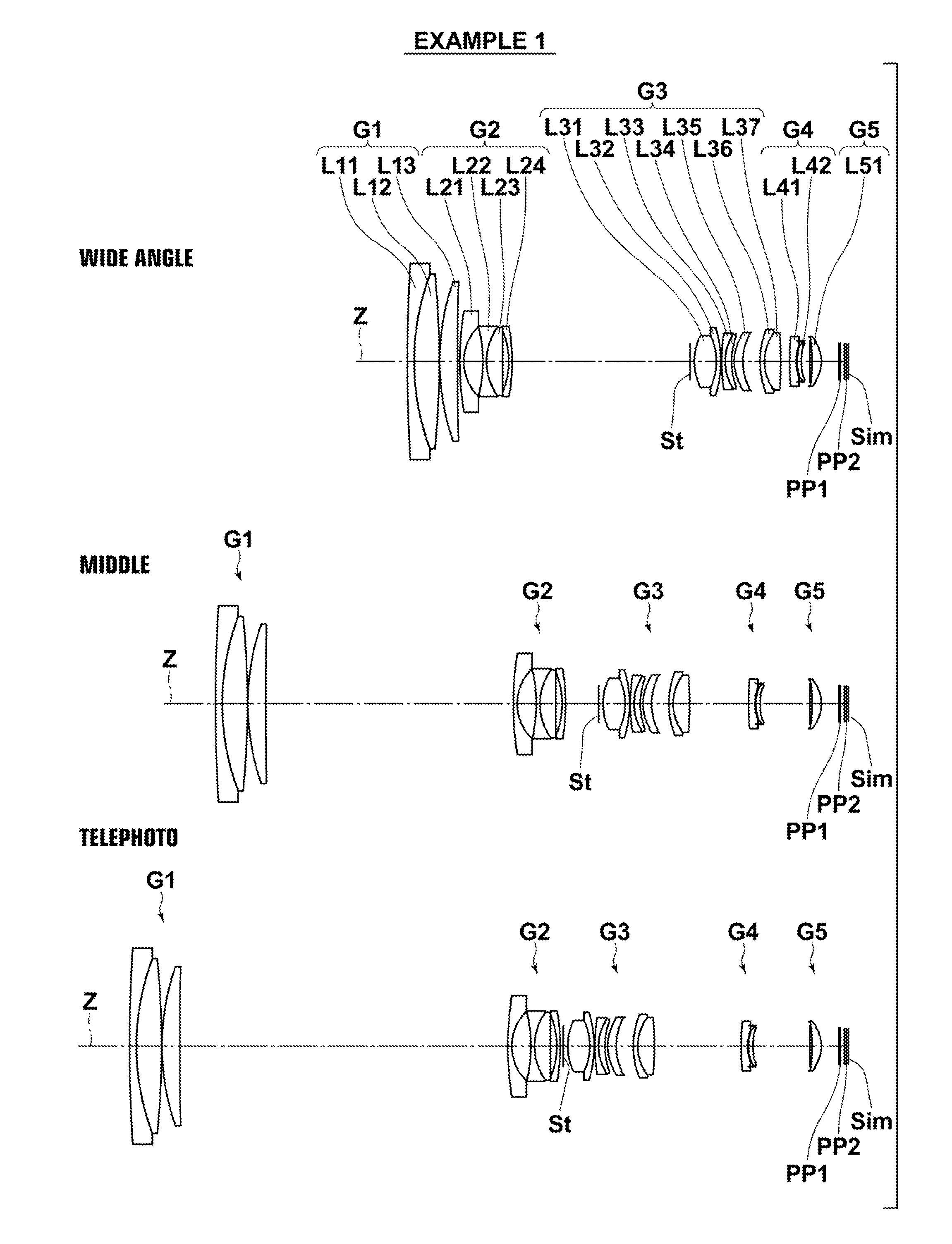
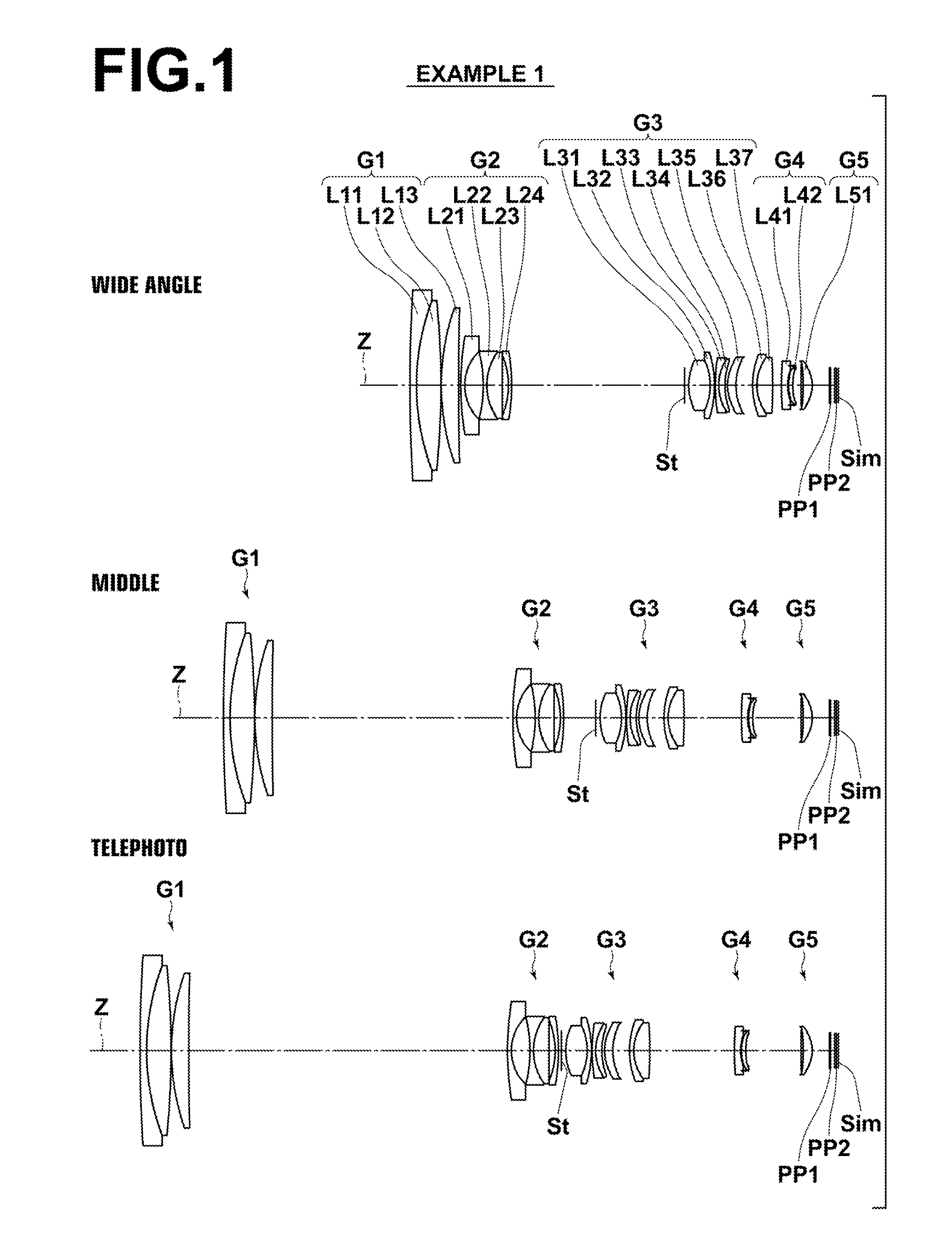
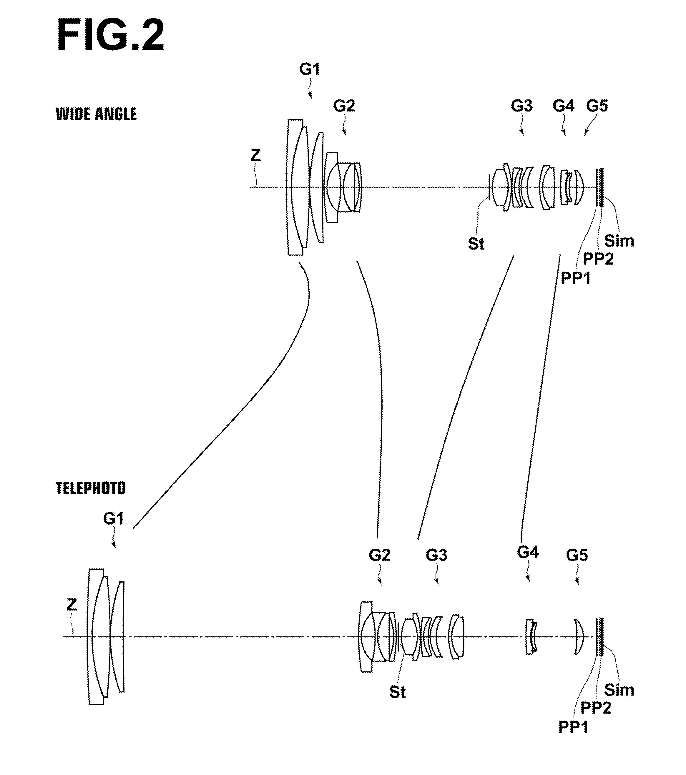
);

[0048]FIG. 2 is a cross section illustrating paths of movement of lens groups in the zoom lens;

[0049]FIG. 3 is a cross section illustrating the lens configuration of a zoom lens in Example 2 of the present invention;

[0050]FIG. 4 is a cross section illustrating the lens configuration of a zoom lens in Example 3 of the present invention;

[0051]FIG. 5 is a cross section illustrating the lens configuration of a zoom lens in Example 4 of the present invention;

[0052]FIG. 6 is a cross section illustrating the lens configuration of a zoom lens in Example 5 of the present invention;

[0053]FIG. 7 is a cross section illustrating the lens configuration of a zoom lens in Example 6 of the present invention;

[0054]FIG. 8 is aberration diagrams (Sections A through L) of the zoom lens in Example 1 of the present invention;

[0055]FIG. 9 is aberration diagrams (Sections A through L) of the zoom lens in Example 2 of the present invention;

[0056]FIG. 10 is aberration diagrams (Sections A through L) of the ...


PUM


Abstract

A zoom lens consists of a first lens group having positive refractive power, a second lens group having negative refractive power, a third lens group having positive refractive power, a fourth lens group having negative refractive power, and a fifth lens group having positive refractive power in this order from an object side. The third lens group includes a cemented lens closest to the object side and a cemented lens closest to an image side, and the fourth lens group consists of a negative lens and a positive lens in this order from the object side. Distances between the lens groups change, and the fifth lens group is fixed, and at least the first lens group and the fourth lens group move when magnification is changed from the wide angle end to the telephoto end.

Description

CROSS-REFERENCE TO RELATED APPLICATIONS[0001]This application is a Continuation of PCT International Application No. PCT / JP2013 / 005323 filed on Sep. 9, 2013, which claims priority under 35 U.S.C. §119(a) to Japanese Patent Application No. 2012-202354 filed on Sep. 14, 2012. Each of the above applications is hereby expressly incorporated by reference, in its entirety, into the present application.BACKGROUND OF THE INVENTION[0002]1. Field of the Invention[0003]The present invention relates to a zoom lens and an imaging apparatus. In particular, the present invention relates to a zoom lens used in an electronic camera, such as a digital camera, a camera for broadcasting, a camera for surveillance and a camera for film making, and also to an imaging apparatus including the zoom lens.[0004]2. Description of the Related Art[0005]In zoom lenses used in imaging apparatuses, such as a video camera and an electronic still camera using imaging devices, such as a CCD (Charge Coupled Device) and...

Claims


Application Information

Patent Timeline
Patent Type & Authority Applications(United States)
IPC IPC(8): G02B15/163G02B27/64
CPCG02B27/646G02B15/163G02B15/20G02B15/145121G02B15/173
Inventor SAITO, HIROKI
Owner FUJIFILM CORP
Why Eureka
Try Eureka