Imaging lens and imaging apparatus

an imaging lens and imaging technology, applied in the field of imaging lenses and imaging apparatuses, can solve the problems of tougher requirements for imaging lenses mounted on in-vehicle cameras, surveillance cameras or the like, and achieve the effects of low cost, wide angle of view, and small siz

Inactive Publication Date: 2014-02-27
NANCHANG O FILM OPTICAL ELECTRONICS TECH CO LTD
View PDF1 Cites 1 Cited by
  • Summary
  • Abstract
  • Description
  • Claims
  • Application Information

AI Technical Summary

Benefits of technology

[0066]According to the first imaging lens of the present invention, the arrangement of power in the entire system, the shapes of the surfaces of the third lens and the fourth lens, and the like are appropriately set, and conditional formula (6) is satisfied in the lens system including at least four lenses. Therefore, it is possible to achieve small size, low cost, and a wide angle of view. Further, it is possible to realize an imaging lens having high optical performance in which curvature of field, a spherical aberration, a coma aberration and distortion are excellently corrected, and an excellent image is obtainable also in a peripheral portion of an image formation area.
[0067]According to the second imaging lens of the present invention, the arrangement of power in the entire system, the shapes of the surfaces of the second lens, the third lens and the fourth lens, and the like are appropriately set, and conditional formula (6-1) is satisfied in the lens system including at least four lenses. Therefore, it is possible to achieve small size, low cost, and a wide angle of view. Further, it is possible to realize an imaging lens having high optical performance in which curvature of field, a spherical aberration, a coma aberration and distortion are excellently corrected, and an excellent image is obtainable also in a peripheral portion of an image formation area.
[0068]According to the third imaging lens of the present invention, the arrangement of power in the entire system, the shapes of the surfaces of the third lens and the fourth lens, and the like are appropriately set, and conditional formula (7) is satisfied in the lens system including at least four lenses. Therefore, it is possible to achieve small size, low cost, and a wide angle of view. Further, it is possible to realize an imaging lens having high optical performance in which curvature of field, a spherical aberration, a coma aberration and distortion are excellently corrected, and an excellent image is obtainable also in a peripheral portion of an image formation area.
[0069]According to the fourth imaging lens of the present invention, the arrangement of power in the entire system, the shapes of the surfaces of the second lens, the third lens and the fourth lens, and the like are appropriately set, and conditional formula (7-1) is satisfied in the lens system including at least four lenses. Therefore, it is possible to achieve small size, low cost, and a wide angle of view. Further, it is possible to realize an imaging lens having high optical performance in which curvature of field, a spherical aberration, a coma aberration and distortion are excellently corrected, and an excellent image is obtainable also in a peripheral portion of an image formation area.
[0070]The imaging apparatus of the present invention includes the imaging lens of the present invention. Therefore, the imaging apparatus is structurable in small size and at low cost. Further, the imaging apparatus has a sufficiently wide angle of view, and can obtain an excellent image with high resolution by using an imaging device.

Problems solved by technology

Meanwhile, requirements for an imaging lens to be mounted on an in-vehicle camera, a surveillance camera or the like have become tougher every year.

Method used


Image

  • Imaging lens and imaging apparatus
  • Imaging lens and imaging apparatus
  • Imaging lens and imaging apparatus

Examples


first embodiment

[0139]Further, the imaging lens according to the present invention satisfies the following conditional formula (6):

0.75≦(R8−R9) / (R8+R9)≦1.0  (6), where

[0140]R8: a curvature radius of an object-side surface of fourth lens L4, and

[0141]R9: a curvature radius of an image-side surface of fourth lens L4.

[0142]When the upper limit and the lower limit of conditional formula (6) are satisfied, fourth lens L4 can have a plano-convex shape having a convex surface directed toward an image side or a meniscus shape having a convex surface directed toward the image side. Therefore, it is possible to excellently correct curvature of field and a spherical aberration. When the upper limit of conditional formula (6) is satisfied, the object-side surface of fourth lens L4 can be a flat surface or a concave surface. Therefore, it is possible to prevent the power of fourth lens L4 from becoming too strong, and to easily provide a long back focus. When the lower limit of conditional formula (6) is satisf...

second embodiment

[0147]Further, the imaging lens according to the present invention satisfies the following conditional formula (6-1):

0.60≦(R8−R9) / (R8+R9)≦1.0  (6-1).

[0148]When second lens L2 has a biconcave shape, it is possible to easily increase the power of second lens L2, and second lens L2 can sharply bend rays. Therefore, it is possible to reduce the angle of incidence of rays entering fourth lens L4. Therefore, even if the lower limit is 0.60, it is possible to suppress the angle of incidence of rays entering a sensor in a peripheral area. When the upper limit and the lower limit of conditional formula (6-1) are satisfied, fourth lens L4 can have a plano-convex shape having a convex surface directed toward an image side or a meniscus shape having a convex surface directed toward the image side. Therefore, it is possible to excellently correct curvature of field and a spherical aberration. When the upper limit of conditional formula (6-1) is satisfied, the object-side surface of fourth lens L...

third embodiment

[0152]Further, the imaging lens according to the present invention satisfies the following conditional formula (7):

6.2R8 / f|  (7), where

[0153]R8: a curvature radius of an object-side surface of fourth lens L4, and

[0154]f: a focal length of an entire system.

[0155]When the lower limit of conditional formula (7) is satisfied, correction of a spherical aberration becomes easy.

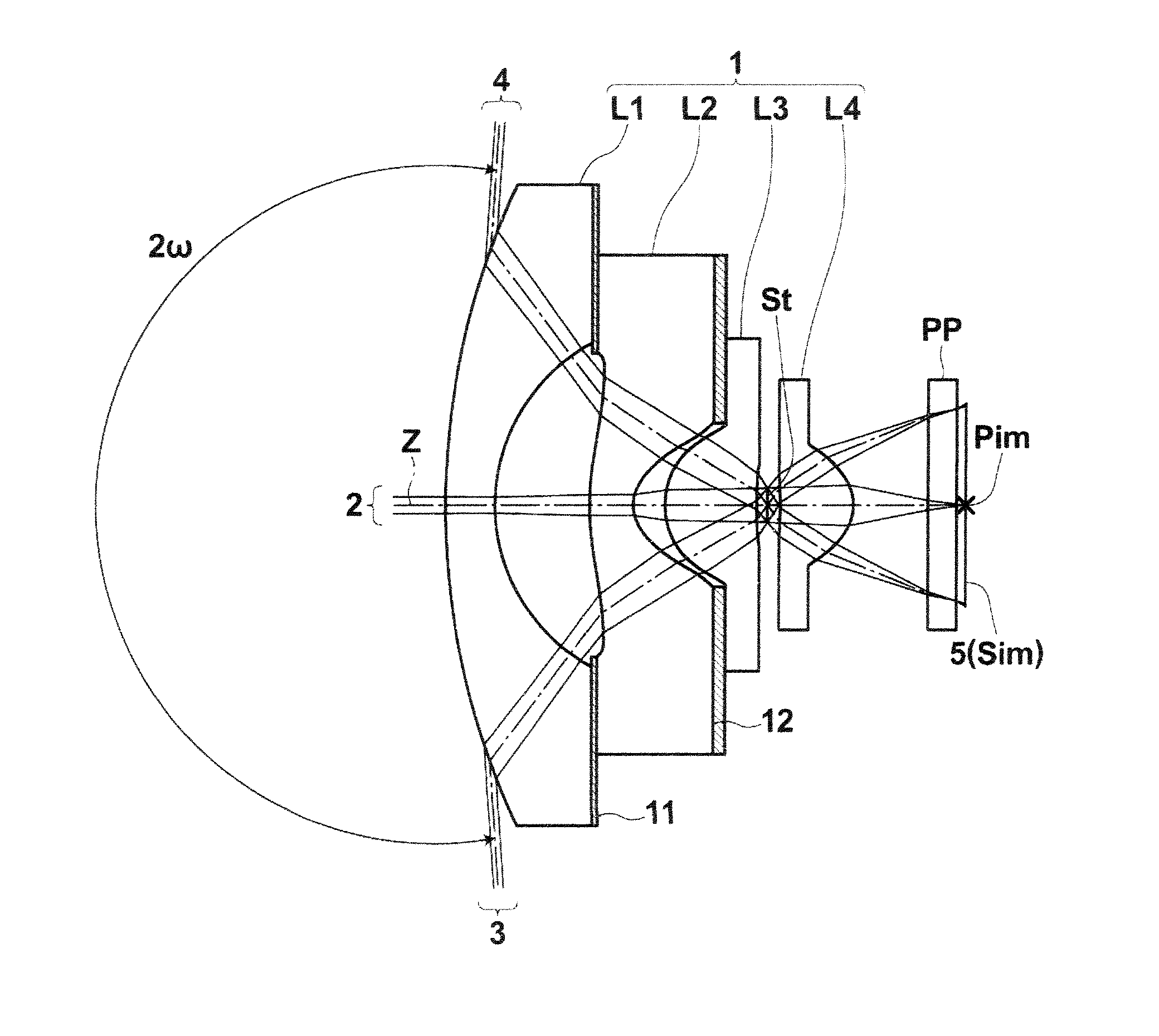
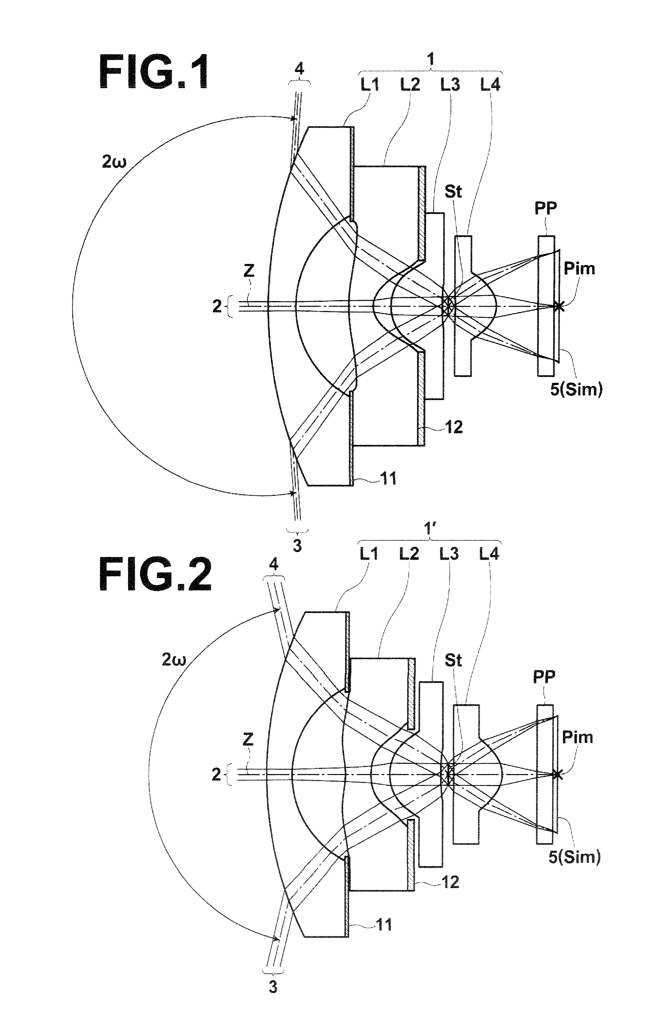
[0156]Next, the structure of a fourth embodiment of the present invention will be described. An imaging lens according to the fourth embodiment of the present invention includes negative first lens L1, negative second lens L2 of a biconcave shape, third lens L3 of a plano-convex shape having a convex surface directed toward an object side or of a positive meniscus shape having a convex surface directed toward the object side, and fourth lens L4 of a plano-convex shape having a convex surface directed toward an image side or of a positive meniscus shape having a convex surface directed toward the image side, which ar...


PUM


Abstract

An imaging lens includes negative first lens, negative second lens, third lens of a plano-convex shape having a convex surface directed toward an object side or of a positive meniscus shape having a convex surface directed toward the object side, and a fourth lens of a plano-convex shape having a convex surface directed toward an image side or of a positive meniscus shape having a convex surface directed toward the image side, which are arranged in this order from the object side. Further, the following conditional formula (6) is satisfied:
0.75≦(R8−R9)/(R8+R9)≦1.0  (6), where
    • R8: a curvature radius of an object-side surface of the fourth lens, and
    • R9: a curvature radius of an image-side surface of the fourth lens.

Description

CROSS REFERENCE TO RELATED APPLICATIONS[0001]This application is a Bypass continuation of PCT / JP2012 / 002901 filed on Apr. 27, 2012, which claims foreign priority to Japanese Application No. 2011-101180 filed on Apr. 28, 2011. The entire contents of each of the above applications are hereby incorporated by reference.BACKGROUND OF THE INVENTION[0002]1. Field of the Invention[0003]The present invention relates to an imaging lens and an imaging apparatus. In particular, the present invention relates to an imaging lens appropriate for use in an in-vehicle camera, a camera for a mobile terminal, a surveillance camera, or the like using an imaging device, such as a CCD (Charge Coupled Device) and a CMOS (Complementary Metal Oxide Semiconductor). Further, the present invention relates to an imaging apparatus including the imaging lens.[0004]2. Description of the Related Art[0005]In recent years, the size of an imaging device, such as a CCD and a CMOS, became small, and the resolution of the...

Claims


Application Information

Patent Timeline
Patent Type & Authority Applications(United States)
IPC IPC(8): G02B13/00
CPCG02B13/004G02B13/06G02B13/04G02B9/34
Inventor ASAMI, TARO
Owner NANCHANG O FILM OPTICAL ELECTRONICS TECH CO LTD
Why Eureka
Try Eureka