Rotating bezel system

a technology of rotating bezels and rotating bezels, which is applied in the field of rotating bezels, can solve the problems of affecting the wear resistance of precious materials, so as to improve the manufacturing process, improve the wear resistance, and avoid premature wear.

Active Publication Date: 2015-07-02
OMEGA SA
View PDF11 Cites 11 Cited by
  • Summary
  • Abstract
  • Description
  • Claims
  • Application Information

AI Technical Summary

Benefits of technology

[0012]A first advantage of the present invention is that the rotating bezel system according to the present invention is simpler to make and to assemble. Indeed, the fact of mounting the ring on a support piece so as to place the spring ring and the toothing between said support piece and the bezel makes it possible to have an independent module: this module improves the manufacturing process, since the rotating bezel modules can be mounted separately. Since the toothing is arranged to be secured to the watch case band, the support piece and the spring are integral with each other.
[0013]Further, this arrangement makes it possible to make bezels from precious materials with no risk of premature wear since the toothing is not integrated in the bezel and is simply secured to said bezel. Indeed, the rotating bezel system is arranged so that the spring and the toothing are inserted between the bezel and the support piece, the spring and the toothing cooperating with each other.
[0014]In a first embodiment, the toothed element and the spring means are concentric to each other.
[0015]In a second embodiment, the bezel and the support element are arranged so that both exhibit a complementary profile such that the assembly of the bezel to the support element defines a first housing in which the toothed element are the spring means are placed.
[0016]In a third embodiment, the toothed element is formed of a toothed ring including a toothing, the spring means including a spring ring which includes elastic means capable of cooperating with the toothing arranged on said toothed element.
[0017]In a fourth embodiment, the toothed ring and the spring ring are flat coplanar rings.

Problems solved by technology

This vertical force has a tendency to push the bezel off the case band of the timepiece.
However, the precious materials have unsuitable mechanical characteristics, such as for example low mechanical resistance.
A snap-fit arrangement using precious materials thus has the drawback of being subject to rapid wear.
The drawback of this solution is that it requires a more complex manufacturing method since the snap-fit arrangement must be made separately and then fixed to the bottom surface of the bezel.
Further, rotating bezel systems have the drawback of being difficult to assemble to the case band since the spring means must be mounted first.
Thus, not only is the assembly complex, but disassembly is virtually impossible and is liable to destroy the rotating bezel.
These systems also have an unattractive operating noise which is bothersome for high end timepieces.

Method used


Image

  • Rotating bezel system
  • Rotating bezel system
  • Rotating bezel system

Examples


first embodiment

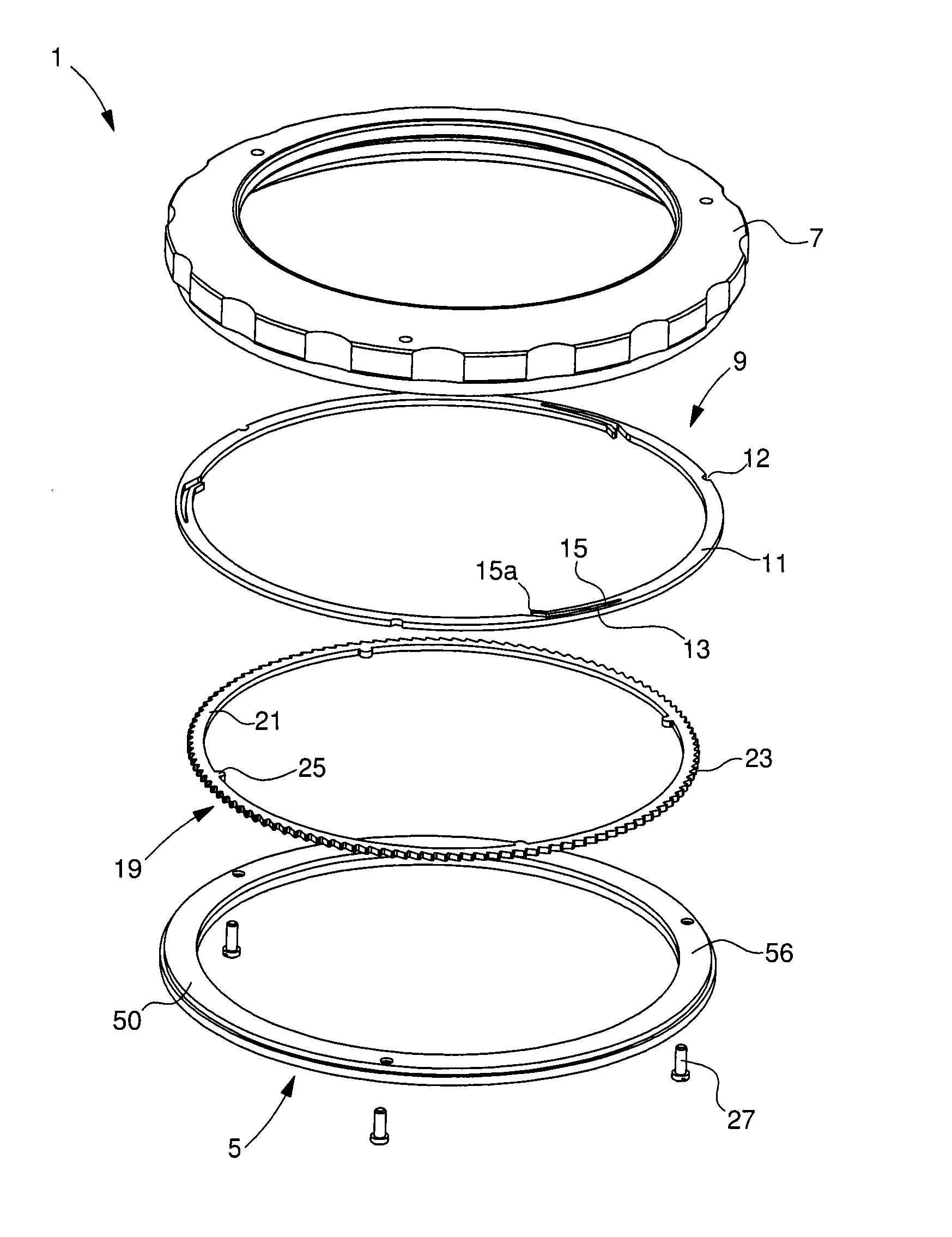
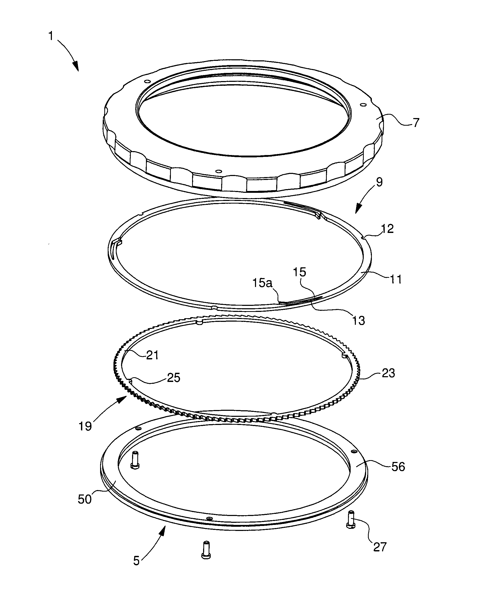
[0041]FIG. 1 shows the rotating bezel system 1 according to the invention in an exploded view to show each part separately.

[0042]In this first embodiment, the rotating bezel system includes a bezel 7, which is the part visible to and handled by the user. This annular bezel includes a top surface 7a visible to the user and a bottom surface 7b. The rotating bezel system 1 further includes a support or pre-assembly element 5 taking the form of an annular ring. This support element 5 includes a flat ring 50 having a top surface 52 and a bottom surface 54. Top surface 52 includes a first peripheral rim 56. Bottom surface 54 includes a second peripheral rim 58 and a third rim 60 close to the inner end of ring 50. Second rim 58 and third rim 60 thus define an annular housing 62. The third rim 60 includes at least one protuberance 64 extending towards the central axis of ring 50. Preferably, third rim 60 includes a single protuberance covering the whole of said rim 60.

[0043]The rotating bez...

second embodiment

[0056]In a second embodiment seen in FIG. 7, rotating bezel system 1 includes a bezel 1070, which is the part visible to and handled by the user. This annular bezel includes a top surface visible to the user and a bottom surface. The rotating bezel system 1 further includes a support element 1050. This support element 1050 includes a flat ring 1051 having a top surface and a bottom surface. The top surface includes a first peripheral rim 1052 having a stair-shaped profile. It is thus clear that said rim has several levels or support surfaces. As a minimum, the first peripheral rim 1052 will include at least an intermediate level, and support element 1050 therefore includes three support surfaces at three different heights. The bottom surface includes a second peripheral rim 1053. The latter has a recess 1054 covering the inner surface of second rim 1053 so as to form a circular recess. Bezel 1070 also has a stair-shaped profile, but inverted. This stair-shaped profile is arranged to...


PUM


Abstract

A timepiece case band including a peripheral shoulder in which an annular rotating bezel system is rotatably mounted. The rotating bezel system is an independent module including an annular bezel, an annular support element, a toothed element, and a spring mechanism cooperating elastically with a snap-fit mechanism, the spring mechanism and the toothed element being axially retained by the bezel and/or the support element. The rotating bezel system further includes a securing mechanism securing the spring mechanism, support element, and bezel to each other.

Description

[0001]The present invention concerns a timepiece comprising a case band closed by a back cover and a crystal, said timepiece further comprising a rotating bezel system secured to said case band.[0002]The technical field of the invention is the technical field of fine mechanics.BACKGROUND OF THE INVENTION[0003]The present invention concerns a rotating bezel for a timepiece.[0004]Known rotating bezel systems include an annular rotating bezel having a top surface and a bottom surface, with the top surface being the surface visible to the user. This bezel has notches or toothing on the bottom surface thereof. The rotating bezel system further includes a spring means. This spring means is inserted between the rotating bezel and the case band of the timepiece when the bezel is snap-fitted onto the case band of the timepiece. This spring means takes the form of a flat ring comprising leaves on the surface thereof facing the notches in the bezel. These leaves are arranged to tilt between 0°...

Claims


Application Information

Patent Timeline
Patent Type & Authority Applications(United States)
IPC IPC(8): G04B19/28
CPCG04B19/283
Inventor SILVANT, OLIVIER
Owner OMEGA SA
Why Eureka
Try Eureka