Acquisition, Tracking, and Pointing Apparatus for Free Space Optical Communications with Moving Focal Plane Array

a technology of optical communication and moving focal plane, applied in the field of optical wireless communication, can solve the problems of gimbal-based fso systems that may be quite heavy, gimbal-based systems may also be bulky, gimbal-based systems may require the use of a great deal of electrical power, and far more power

Active Publication Date: 2015-07-02
SPACE PHOTONICS
View PDF58 Cites 53 Cited by
  • Summary
  • Abstract
  • Description
  • Claims
  • Application Information

AI Technical Summary

Benefits of technology

[0008]The present invention is directed to an FSO system and ATP components for an FSO system using a multi-element array of photo-detectors positioned in the focal plane of an optical transmitter, receiver, or transceiver telescope. As an optical signal is received in the telescope, that signal is detected on certain elements of the multi-element focal plane detector array. In response, the focal plane detector array may be repositioned within the focal plane of the telescope. In certain implementations, a high-speed optical detector, an optical transmitter diode, an optical fiber, or other optical communications element may be positioned at the center of the multi-element detector array. The detector array is manipulated such that the light signal input maximum is aligned with the optical communications element. In this way, the telescope may be aligned without the use of traditional “beam steering” techniques.
[0009]By noting the x-y position of the incoming signal on the telescope focal plane based on the elements of the multi-element detector array that receive that signal, the angle of a remote incoming optical signal may be detected, and that information may be used to control the movement of the optical communications element to the location of the arriving remote terminal optical signal. The invention simplifies FSO systems by eliminating the need for beam splitters and prisms that would be required if a multi-element array detector were employed as a wavefront detector and implemented remotely from the transmitter. In contrast to the present invention, this alternative approach would require two separate optical paths and relatively complex optical component design, and could require mirrors for 90-degree turns.

Problems solved by technology

Gimbal-based FSO systems may be quite heavy due to the weight of the mechanical components, motors, and servos.
Gimbal-based systems may also be bulky due to the required mechanical components.
Finally, mechanical gimballing systems may require the use of a great deal of electrical power, far more power than is typically consumed by the electronics associated with an optical receiver or transmitter system.

Method used


Image

  • Acquisition, Tracking, and Pointing Apparatus for Free Space Optical Communications with Moving Focal Plane Array
  • Acquisition, Tracking, and Pointing Apparatus for Free Space Optical Communications with Moving Focal Plane Array
  • Acquisition, Tracking, and Pointing Apparatus for Free Space Optical Communications with Moving Focal Plane Array

Examples


Embodiment Construction

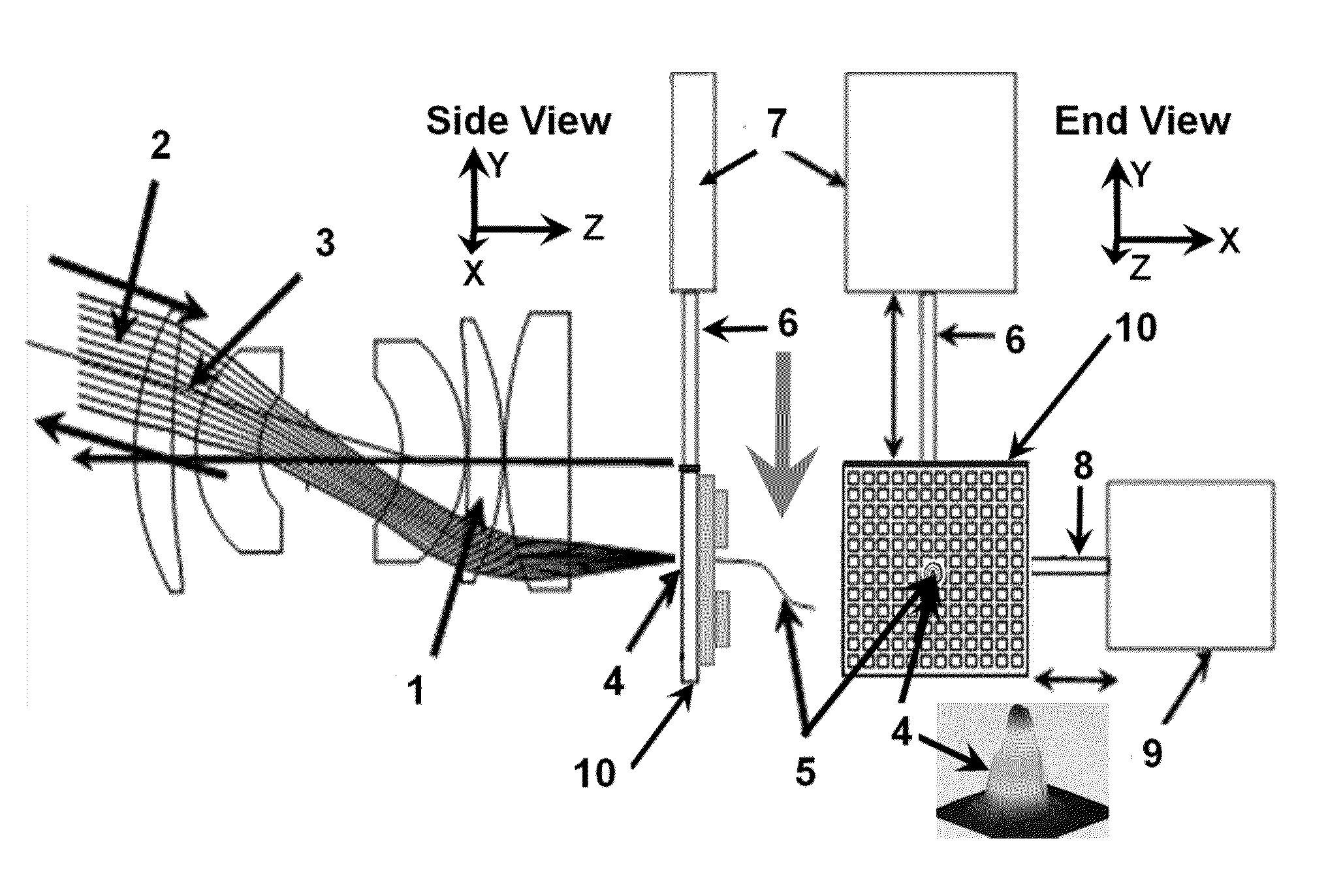
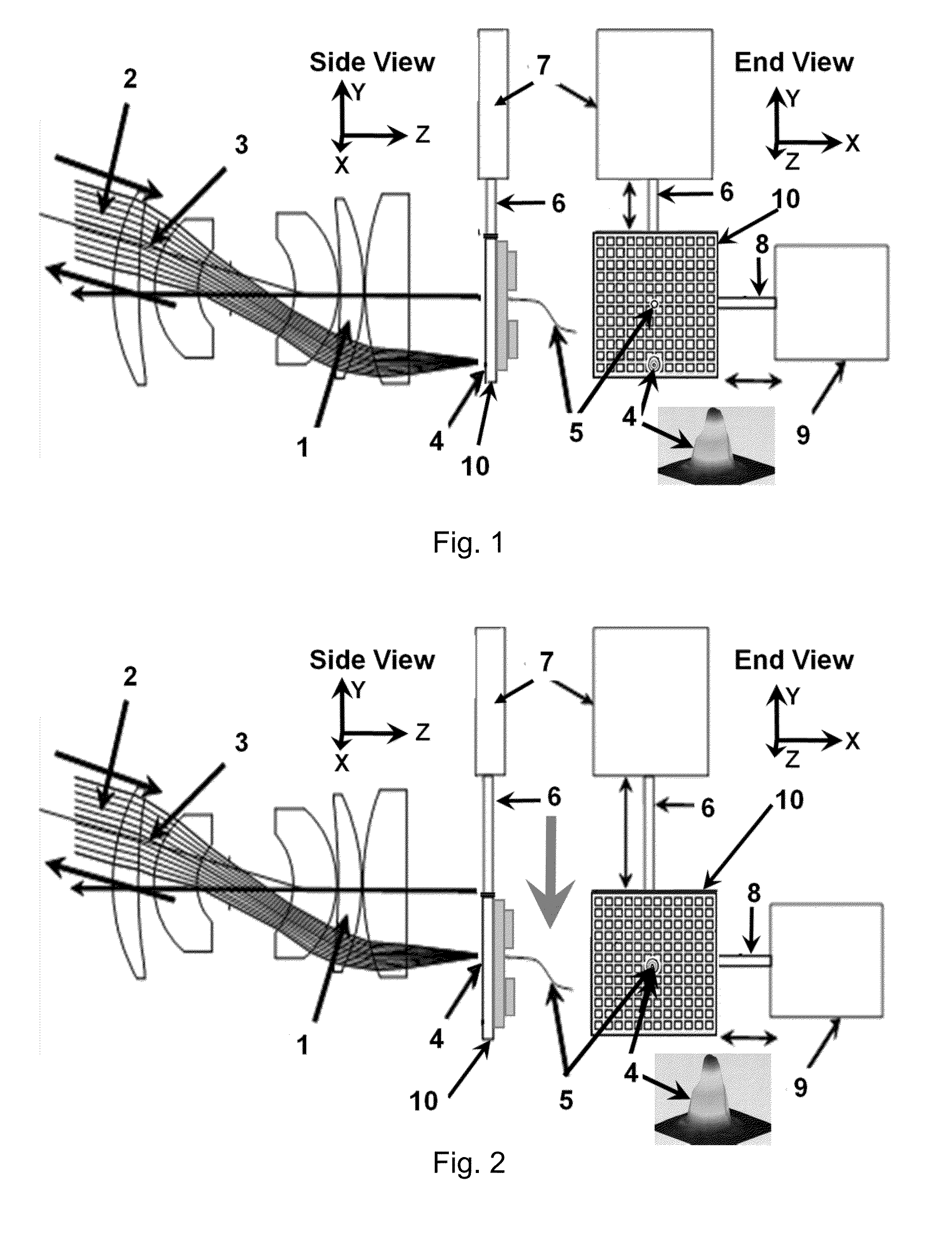
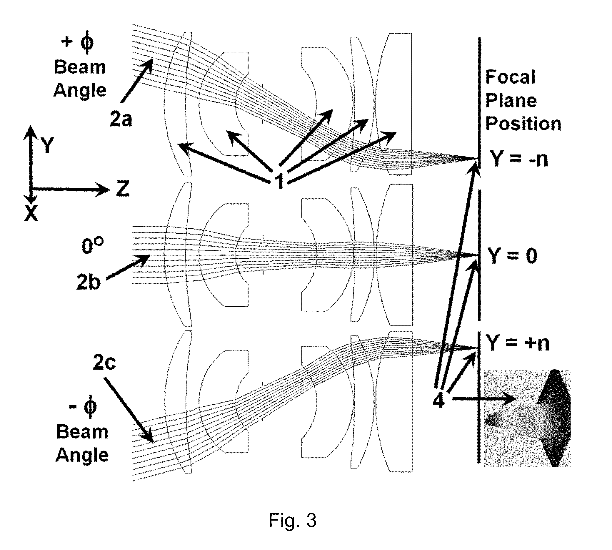
[0018]With reference to FIGS. 1 through 7, an implementation of the present invention may now be described. A laser communications transceiver incorporating the rapid acquisition, tracking and pointing (ATP) system is described herein, but the invention is not so limited, and in fact may be put to other applications where the ATP function is desired. The optical system of FIGS. 1 through 7 consists of beam expansion optics and focusing optical design that provides angle of arrival direction measurement and controlled motion in the focal plane that provide immediate alignment of the incoming optical beam. Additionally, for a transmitter telescope, it provides controlled motion in the focal plane that aligns precisely the outgoing transmitted beam in the direction of an incoming optical beam from a remote optical terminal.

[0019]The focal plane contains an array of photo-detectors of precise size to provide a correspondingly precise measurement of the position of a focused optical beam...


PUM


Abstract

An acquisition, pointing, and tracking (ATP) apparatus for free space optical (FSO) communications systems incorporates a multi-element detector array positioned at a focal plane of an optical telescope. An optical communications element lies at the center of the detector array. In lieu of traditional beam steering, the apparatus performs pointing and tracking functions internally by first calculating a position of an optical maximum on the detector array, and then translating the detector array within the focal plane of the telescope such that the optical communications element lies at the optical maximum for transmitting and / or receiving optical communications signals.

Description

CROSS-REFERENCE TO RELATED APPLICATIONS[0001]This application claims the benefit of U.S. provisional patent application No. 61 / 921,331, filed Dec. 27, 2013, for “Rapid Free Space Optical Link Acquisition with Moving Focal Plane Containing an Array of Detectors.” Such application is incorporated herein by reference in its entirety.BACKGROUND[0002]The present invention relates to the field of optical wireless communications, and in particular to acquisition, tracking, and pointing (ATP) systems for free space optical (FSO) communications.[0003]FSO systems employ light propagating in free space to transmit data without using a connecting cable or transmission line. An FSO system typically consists of a set of two transmitting terminals and receiving terminals or transceiver terminals. Electrical communication signals are converted to optical signals, and then transmitted from the telescope of the transmitting optical terminal. The receiving terminal receives the incoming optical signal...

Claims


Application Information

Patent Timeline
Patent Type & Authority Applications(United States)
IPC IPC(8): H04B10/112
CPCG02B23/16H04B10/112G02B13/22G02B23/00
Inventor CHALFANT, III, CHARLES H.TIDWELL, TERRYLEARY, MICHAELBORSODI, LIAM
Owner SPACE PHOTONICS
Why Eureka
Try Eureka