Stand module and mobile terminal including the stand module

a technology of mobile terminal and stand module, which is applied in the field of mobile terminal, can solve the problems of user inconvenience of viewing moving images on a mobile terminal

Inactive Publication Date: 2015-07-16
LG ELECTRONICS INC
View PDF7 Cites 9 Cited by
  • Summary
  • Abstract
  • Description
  • Claims
  • Application Information

AI Technical Summary

Benefits of technology

[0031]Effects of the mobile terminal and the stand module according to the present invention are as follows. According to at least one of the embodiments of the present invention, in a case where the user views a moving image on the mobile terminal, there is an advantage of supporting the mobile terminal without having to adding a component to support the mobile terminal.
[0032]In addition, according to at least one of the embodiments of the present invention, there is an advantage of adjusting an angle of elevation of the mobile terminal according to a user's preference.

Problems solved by technology

On the other hand, the user has the inconvenience of viewing a moving image on a mobile terminal with grasping the mobile terminal with his / her hand.

Method used


Image

  • Stand module and mobile terminal including the stand module
  • Stand module and mobile terminal including the stand module
  • Stand module and mobile terminal including the stand module

Examples


first embodiment

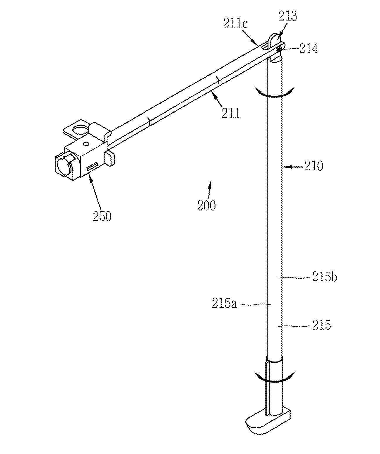
[0157]According to the present invention, the outer circumferential surface of the rod 210 is configured to have at least one flat surface 211a or 211b along an axial direction, and an inner circumferential surface of the body 251 corresponds to the outer circumferential surface of the rod 210 in terms of a form. This configuration enables the rod 210 to moves along the inner circumferential surface of the body 251. A space 211c is formed on the end of the first rod 211 to easily combine the first rod 211 and the second rod 215 with each other. Thus, one end portion of the second rod 215 is inserted into the space 211c and the hinge 214 holds the end portion of the second rod 215 in place.

[0158]If a cross section of the rod 210 along the axial direction is in circular form and an internal hole in the rotation control unit 250 is in cylindrical form, the rod 210 freely rotates with respect to the inner circumferential surface. The insertion portion 252 and the groove 252 are formed t...

second embodiment

[0163]A cross section of the rod 310 may be in circular form. Both flank surfaces of the movement limiting portion 312 are configured to be flat surfaces 312a and 312b with curved surface in between. The flat surfaces 312a and 312b come into contact with the two rotation prevention portions 356, respectively, to prevent the rotation of the rod 310.

[0164]A mating member of the body of the mobile terminal 100 may be configured in such a manner that the movement limiting portion 312 is inserted. FIG. 3E illustrates that a stand module according to the second embodiment is combined with the rear case 102. It is seen from FIG. 3E that the mating member 370 that has a flat surface is also formed on the body of the mobile terminal 100 in order to hold the movement limiting portion 312 in place.

[0165]The cross section of the rod 310 is in circular form, according to the second embodiment, but is not necessarily limited to this. An outer circumferential surface of the rod 310 may have at le...

third embodiment

[0167] the stand module further includes a rotation prevention member 420 that is arranged between the body 451 and a movement limiting portion 412 on an outer circumferential surface of the rod 410 and that has a groove 421 that corresponds to a protrusion 413 in terms of a form. The movement limiting portion 412 that has a larger cross-sectional area than the rod 410 is provided on a lower end of the rod 410 and the protrusion 413 is formed on one portion of an outer circumferential surface of the movement limiting portion 412.

[0168]According to the third embodiment, the movement limiting portion 412 and the rotation prevention member 420 are provided in order to control rotation of the rod 410. The movement limiting portion 412 in the form of a ring is formed on the lower end of the rod 410. The movement limiting portion 412 has the protrusion 413 that protrudes as is the case with first embodiment. The protrusion 413 is inserted into the groove 421 in the rotation prevention mem...


PUM


Abstract

Provided is a stand module including: a rod formed in a body of a mobile terminal so as to extend from the body of the mobile terminal, and supporting the body of the mobile terminal when the rod extends from the body of the mobile terminal; and a rotation control unit that controls rotation of the rod after the rod extends from the body of the mobile terminal, wherein the rod includes: a first rod formed in the body of the mobile terminal, the first rod having one end combined with the rotation control unit; a second rod exposed to the outside of the body of the mobile terminal when extending from the mobile terminal; and a hinge portion that connects the first rod and the second rod with each other, and that serves as an axis about which the second rod rotates with respect to the first rod.

Description

CROSS-REFERENCE TO RELATED APPLICATION[0001]Pursuant to 35 U.S.C. §119(a), this application claims the benefit of earlier filing date and right of priority to Korean Application No. 10-2014-0004759, filed on Jan. 14, 2014, the contents of which is incorporated by reference herein in its entirety.BACKGROUND OF THE DISCLOSURE[0002]1. Field of the Disclosure[0003]The present invention relates to a mobile terminal that includes a stand module supporting the mobile terminal.[0004]2. Background of the Disclosure[0005]A terminal is broadly categorized by mobility into a mobile terminal and a stationary terminal. The mobile terminal is further categorized by portability into a handheld terminal and a vehicle-mounted terminal.[0006]In response to an increasing demand for diversified functions, the terminal has been realized in the form of a multimedia player with multiple functions such as shooting a photographic object as a still image or moving images, reproducing digital audio and video c...

Claims


Application Information

Patent Timeline
Patent Type & Authority Applications(United States)
IPC IPC(8): H05K5/02G06F1/16H01Q1/24
CPCH05K5/0234G06F1/1633H01Q1/244G06F1/1626G06F1/166G06F1/1698H04B1/3877H04M1/04F16L1/161F16L9/22H02G9/04F16M13/00H04B1/38
Inventor LEE, JUNGYUNKIM, JONGHOONLEE, YONGHOKIM, HANGSEOKHONG, SUKHO
Owner LG ELECTRONICS INC
Why Eureka
Try Eureka