Vacuum pump protection net, method for manufacturing the same, and vacuum pump

a vacuum pump and protection net technology, applied in the direction of machines/engines, liquid fuel engines, positive displacement liquid engines, etc., can solve the problems the damage to the protection net itself and the rotor body, etc., to reduce the suction resistance, ensure the attachment strength, and avoid the effect of increasing the size of the vacuum pump

Active Publication Date: 2015-07-23
SHIMADZU CORP
View PDF3 Cites 6 Cited by
  • Summary
  • Abstract
  • Description
  • Claims
  • Application Information

AI Technical Summary

Benefits of technology

[0014]According to the present invention, the thickness of a mesh section of the vacuum pump protection net is equal to or less than half the thickness of the peripheral edge section. Therefore, it is possible to ensure the attachment strength in the peripheral edge section and also reduce the suction resistance in the mesh section without increasing the size of the vacuum pump.

Problems solved by technology

If the deformed part of the protection net abuts on the rotor body of the exhaust structure unit, the protection net itself and the rotor body are damaged.
However, largely separating the protection net from the rotor body increases the size of the vacuum pump.

Method used


Image

  • Vacuum pump protection net, method for manufacturing the same, and vacuum pump
  • Vacuum pump protection net, method for manufacturing the same, and vacuum pump
  • Vacuum pump protection net, method for manufacturing the same, and vacuum pump

Examples


first embodiment

Vacuum Pump

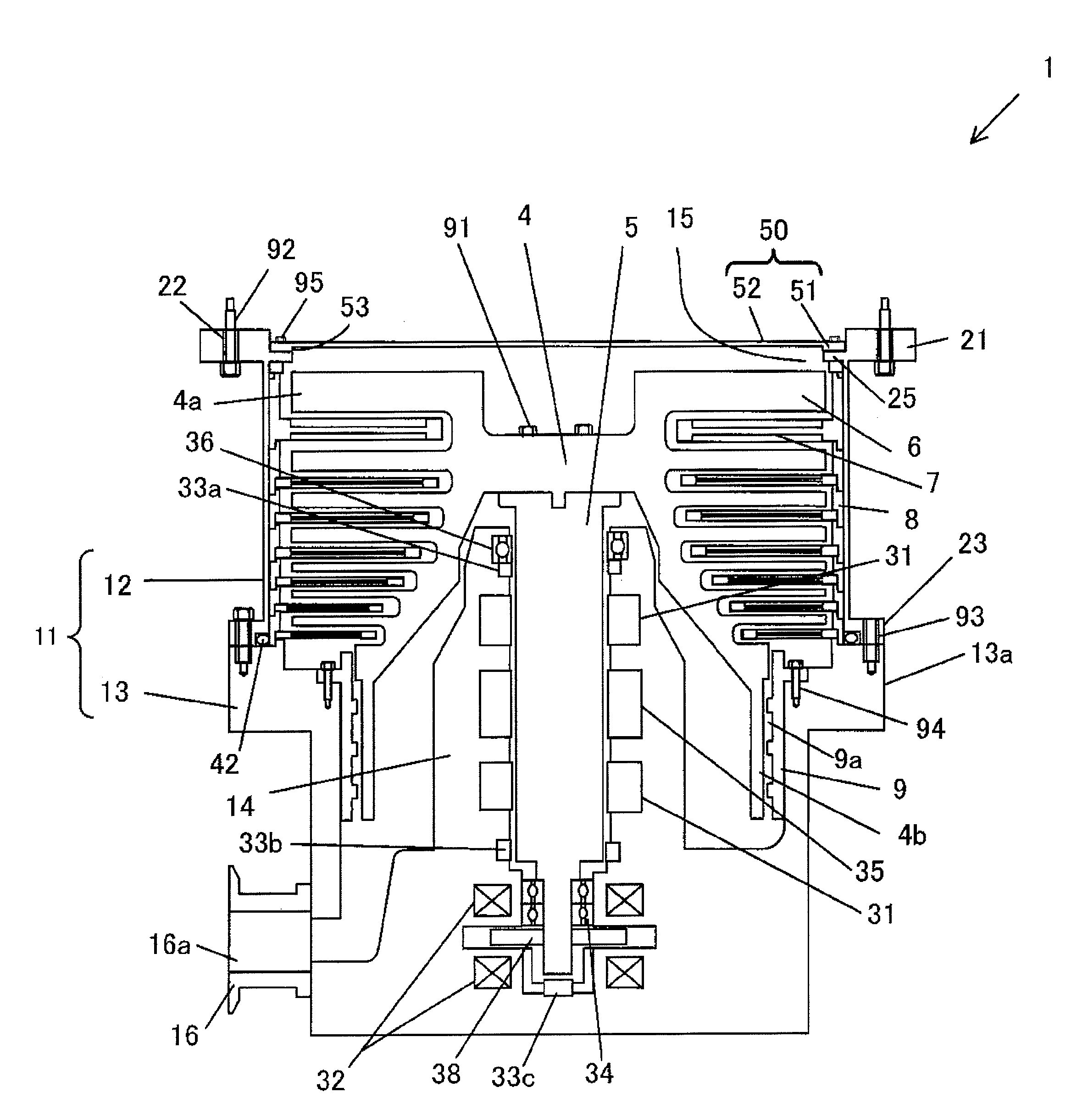
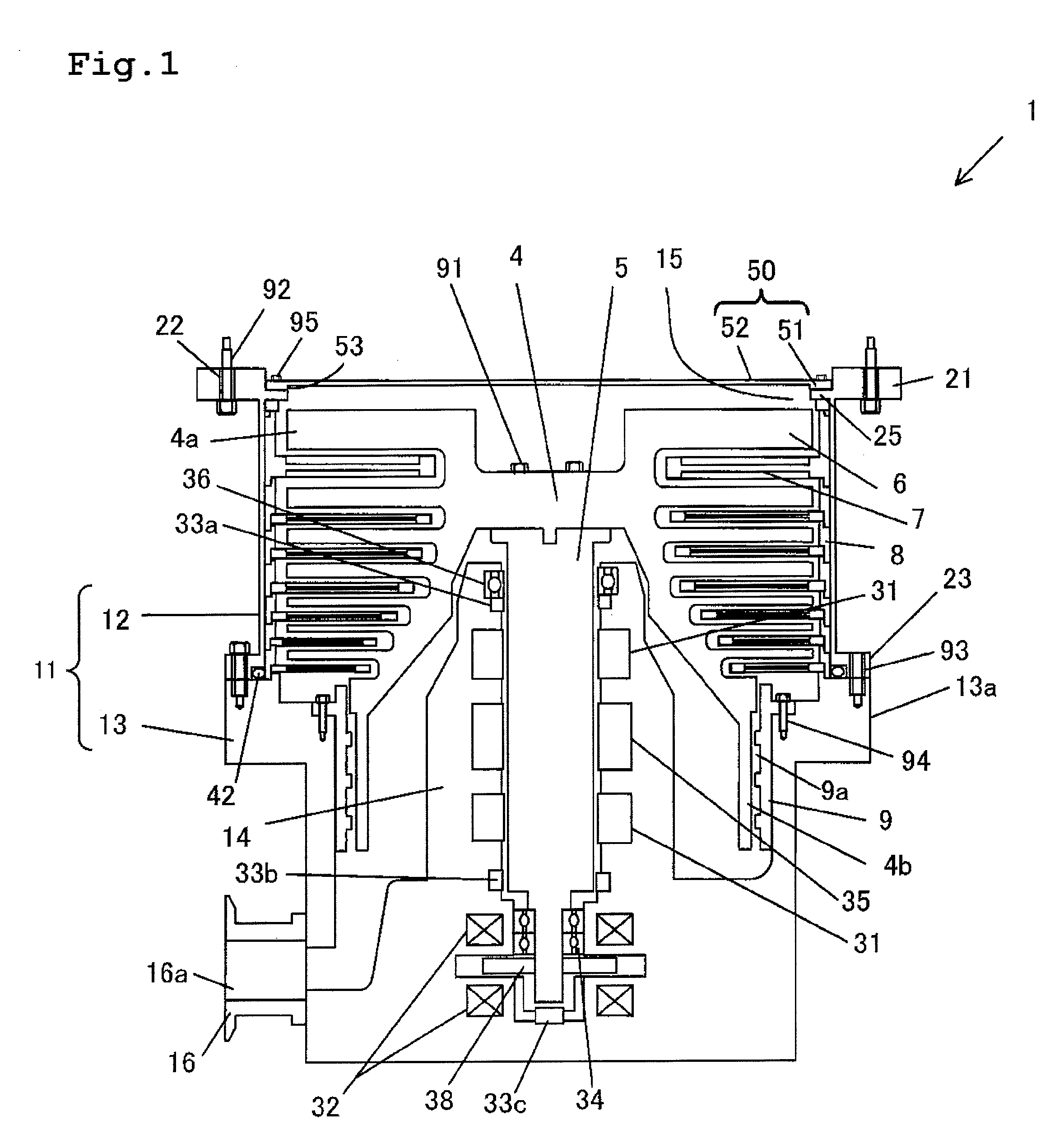
[0025]Hereinbelow, an embodiment of a vacuum pump protection net and a vacuum pump of the present invention will be described with reference to FIGS. 1 to 4(C). FIG. 1 is a cross-sectional view of a turbo-molecular pump as an embodiment of the vacuum pump of the present invention. The turbo-molecular pump 1 is provided with a pump container 11 which includes a case member 12 and a base 13 fixed to the case member 12. The case member 12 has a generally cylindrical shape. The case member 12 is formed of, for example, SUS. An upper flange 21 is formed on an upper end of the case member 12. A circular suction opening 15 is formed on the inner side of the upper flange 21 of the case member 12. The upper flange 21 has bolt insertion through holes 22 which are formed at substantially equal intervals along a circumferential direction. The turbo-molecular pump 1 is attached to an external apparatus, for example, a semiconductor manufacturing apparatus with bolts 92 inserted throug...

second embodiment

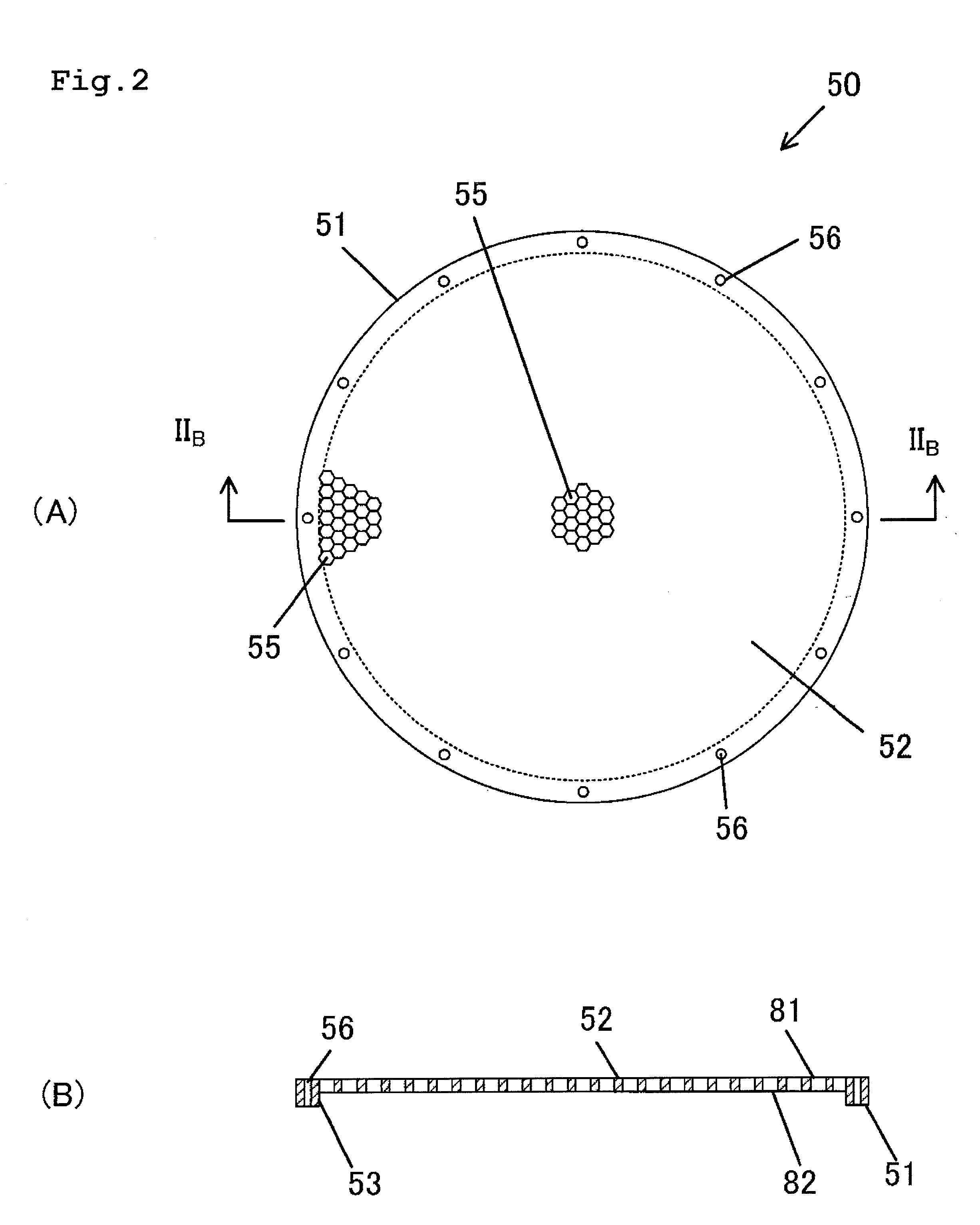
[0045]A second embodiment of the present invention will be described with reference to FIGS. 6(A) to 10. FIG. 6(A) is a plan view of a vacuum pump protection net according to the second embodiment of the present invention. FIG. 6(B) is a cross-sectional view taken along line VIB-VIB in FIG. 6(A). FIG. 7 is an enlarged view of region VII in FIG. 6(A). A protection net 50A of the second embodiment differs from the protection net 50 of the first embodiment in that a reinforcement rib 58 is disposed on a mesh section 52. Hereinbelow, the difference between the second embodiment and the first embodiment will be mainly described. Thus, description of similar points to the first embodiment will not be given by applying identical reference numerals to the corresponding members.

[0046]The reinforcement rib 58 is formed in a cross shape passing through the center of the mesh section 52, and integrally formed with a peripheral edge section 51 and the mesh section 52 using, for example, SUS. A f...


PUM

PropertyMeasurementUnit
thicknessaaaaaaaaaa
thicknessaaaaaaaaaa
thicknessaaaaaaaaaa

Abstract

A vacuum pump protection net 50 is provided with a peripheral edge section 51 and a flat mesh section 52 which is formed on the inner side of the peripheral edge section 51 and has a plurality of through holes 55. The thickness of the mesh section 52 is equal to or less than half the thickness of the peripheral edge section 51. A first surface of the mesh section 52 is located on the same plane as a first surface of the peripheral edge section 52. A second surface of the mesh section 52 is recessed from a second surface of the peripheral edge section 51.

Description

TECHNICAL FIELD[0001]The present invention relates to a vacuum pump protection net, a method for manufacturing the vacuum pump protection net, and a vacuum pump.BACKGROUND ART[0002]A vacuum pump such as a turbo-molecular pump includes an exhaust structure unit which is attached inside a case member, and sucks gas inside a vacuum processing chamber of an external apparatus, for example, a semiconductor manufacturing apparatus through a suction opening and discharges the gas through an exhaust opening by the exhaust structure unit. Generally, a protection net having many minute through holes is disposed on the suction opening of the vacuum pump. The protection net prevents a foreign substance flying from the vacuum processing chamber from entering the inside of the vacuum pump and colliding with members of the exhaust structure unit such as a rotor body. The protection net is deformed to be twisted when the vacuum pump enters the atmosphere and swells toward the exhaust structure unit...

Claims


Application Information

Patent Timeline
Patent Type & Authority Applications(United States)
IPC IPC(8): F04D29/70F04D29/64F04D29/62
CPCF04D29/701F04D29/644F04D29/624F04B37/14F04B37/16F04B39/16F04D19/04F04D19/042Y10T29/49236
Inventor KOGAME, MASAHITO
Owner SHIMADZU CORP
Why Eureka
Try Eureka