
Airbag device

Active Publication Date: 2020-04-23
TOYODA GOSEI CO LTD
View PDF0 Cites 4 Cited by
  • Summary
  • Abstract
  • Description
  • Claims
  • Application Information

AI Technical Summary

Benefits of technology

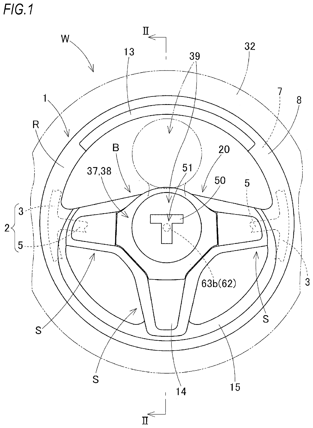
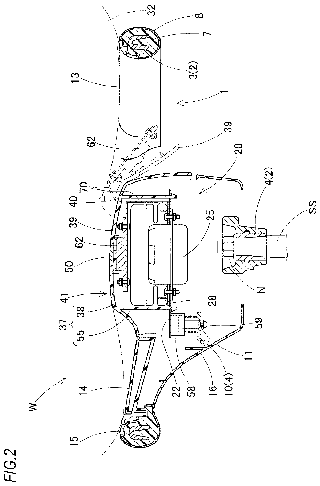
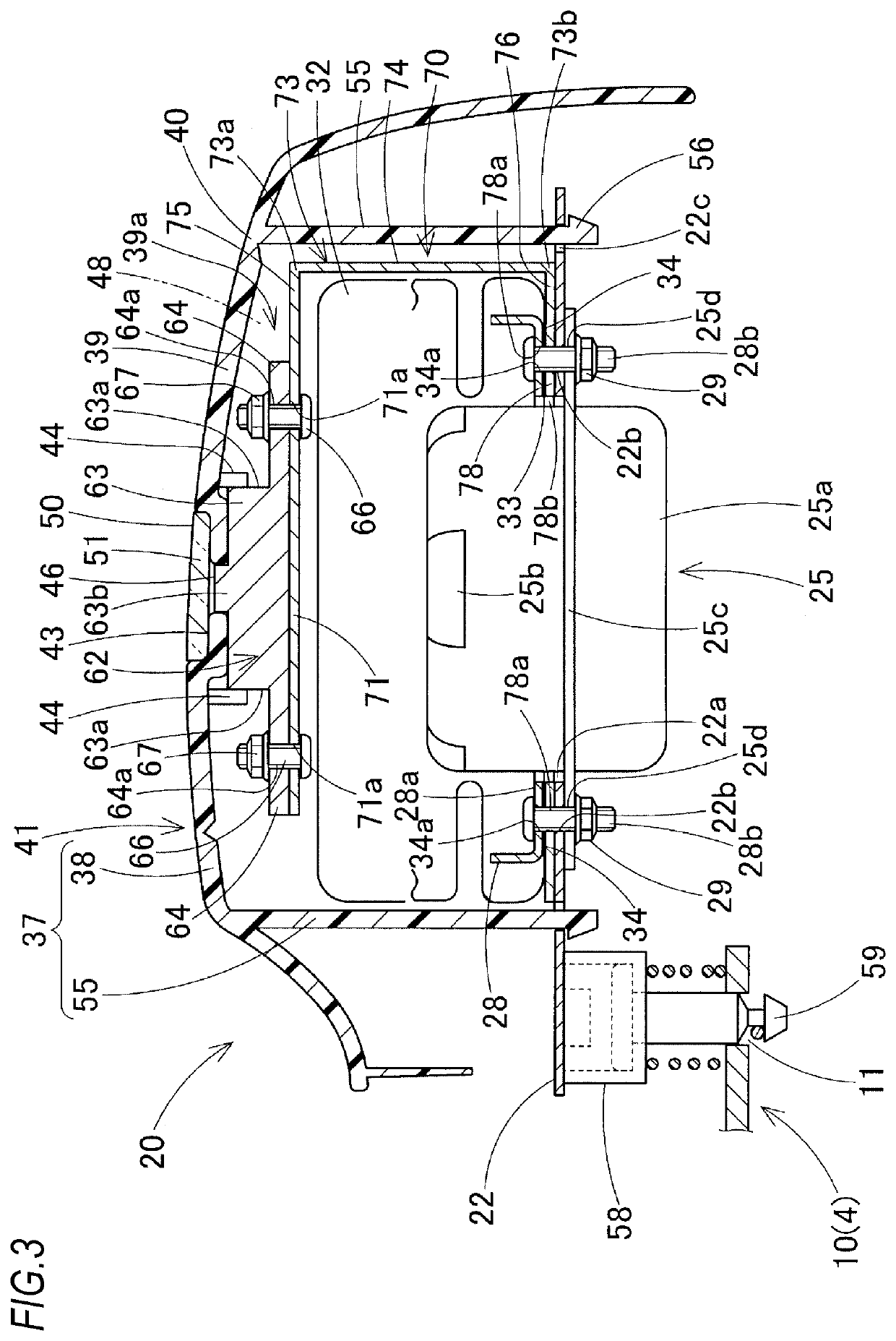
The present invention provides an airbag device that can be easily mounted on a vehicle and reduces reinforcement of a hinge portion of a door portion even if a functional component is provided on the door portion. The airbag device includes an airbag and an airbag cover, and a holder for holding the airbag and airbag cover. The airbag cover has a door portion that is pushed and opened by the inflating airbag. The door portion has an attachment wall portion around its periphery and is connected to a deformable holding member. The holding member has a distal side connecting portion, a proximal side connecting portion, and a deformation portion to reduce the centrifugal force acting on the hinge portion of the door portion. This design allows for easy installation and ensures the functional component's connection and holding while also reducing the risk of injury during airbag deployment.

Problems solved by technology

Further, if the weight of the functional component increases, it cannot be dealt with easily.

Method used


Image

  • Airbag device
  • Airbag device
  • Airbag device

Examples


first embodiment

[0044]In the first embodiment, the holding member 70 is formed of a metal material which is a plate material, a wire material or the like formed of a plastically deformable steel, an aluminum alloy or the like (in the embodiment, formed of a metal plate) and has a U shape. The holding member 70 includes a distal side connecting portion 71 on a distal end portion side to which the camera 62 is connected so as to connect and hold the camera 62, a proximal side connecting portion 78 which is connected to the holder 22, and a deformation portion 73 which is provided between the distal side connecting portion 71 and the proximal side connecting portion 78. An attachment hole 71a for fixing the attachment seat 64 of the camera 62 by the bolt 66 is passed through the distal side connecting portion 71, and the attachment hole 78a, through which each of the bolts 28b of the retainer 28 passes, is formed in the proximal side connecting portion 78. The proximal side connecting portion 78 is sa...

second embodiment

[0069]Therefore, in the airbag device 20B even if the camera 62B, which is the functional component, is provided in the door portion 39 which is pushed and opened by the airbag 32, reinforcement of the hinge portion 40 of the door portion 39 can be reduced and the airbag device 20B can be arranged easily.

[0070]In the second embodiment, the proximal side connecting portion 78B of the holding member 70B is connected to the holder 22. However, the centrifugal force at a time of rotation of the camera 62B which is the functional component may not greatly act on the door portion 39 and the hinge portion 40 of the airbag cover 37B. Therefore, the proximal side connecting portion 78B of the holding member 70B may pass through the holder 22 and may be connected to the boss core metal portion 4 of the core metal 2 of the steering wheel main body 1 or the like.

[0071]As an airbag device 20C illustrated in FIG. 8, a proximal side connecting portion 78C of a holding member 70C may be attached a...


PUM


Abstract

An airbag device includes an airbag, an airbag cover which covers the airbag, and a holder which holds the airbag and the airbag cover. The airbag cover includes a door portion which is pushed by the inflating airbag and opened with a hinge portion around a rotation center. A functional component is provided on the door portion and connected to and held by a deformable holding member. The holding member includes a distal side connecting portion connected to the functional component, a proximal side connecting portion connected to a part which can ensure an attachment strength, and a deformation portion which is provided between the distal and proximal side connecting portions and deformed to maintain a connection and holding state of the distal side connecting portion with the functional component and reduce a centrifugal force of the functional component acting on the hinge portion when the airbag is inflated.

Description

CROSS-REFERENCE TO RELATED APPLICATION[0001]This application claims priority from Japanese Patent Application No. 2018-197647, filed on Oct. 19, 2018, the entire subject matter of which is incorporated herein by reference.TECHNICAL FIELD[0002]The present invention relates to an airbag device which is mounted on a steering wheel or the like, and particularly to an airbag device including a functional component which is provided on a door portion of an airbag cover that is pushed and opened by an inflating airbag.BACKGROUND ART[0003]A related-art airbag device mounted on a vehicle includes an airbag which is unfolded and inflated from a folded state by flowing inflation gas therein, an airbag cover which covers the folded airbag, and a holder which holds the airbag and the airbag cover (see, for example, JP-A-2017-226348). In this airbag device, the airbag cover includes a door portion which is pushed by the inflating airbag and opened with a hinge portion being used as a rotation cen...

Claims


Application Information

Patent Timeline
IPC IPC(8): B60R21/215B60R21/203
CPCB60R21/215B60R2021/21537B60R21/203B60R11/04B60R2011/001B60R21/216
Inventor MURAI, TAKAMITSUKAMEI, SHUNSUKEKIHARA, HISANORI
Owner TOYODA GOSEI CO LTD
Learn More