No-Insulation Multi-Width Winding for High Temperature Superconducting Magnets

a superconducting magnet, no insulation multi-width technology, applied in the field of electromagnetism, can solve the problems of high susceptibility to quench, large size, low thermal stability,

Active Publication Date: 2015-07-30
MASSACHUSETTS INST OF TECH
View PDF18 Cites 21 Cited by
  • Summary
  • Abstract
  • Description
  • Claims
  • Application Information

AI Technical Summary

Benefits of technology

[0009]Embodiments of the present invention provide no-insulation multi-width winding for high temperature superconducting magnets. Briefly described, the present invention is directed to a high-field HTS magnet having a stack of a plurality of double-pancake (DP) coils, each DP coil having a first superconducting coil and a second superconducting coil. The device includes a first DP coil having a first width disposed at a top of the stack, a second DP coil having a second width disposed at a bottom of the stack, and a third DP coil having a third width disposed substantially at a midpoint of the stack. The first width is substantially equal to the second width, and the third width is substantially narrower than the first width. The plurality of superconducting coils may substantially omit a turn-to-turn insulation.

Problems solved by technology

The magnet has three operational challenges: 1) high susceptibility to quench, because of its extremely low thermal stability; 2) large size, because of the low-current carrying capacities of LTS at ≧12 T; and 3) high cryogenic cost, because of its reliance on LHe.
However, except for ensuring a specific current path within a winding, insulation is undesirable in several aspects.
First, the insulation, generally organic, makes a winding elastically soft and increases mechanical strain of the winding under a given stress (“spongy effect”).
Second, insulation reduces the overall current density of the winding.
Third, insulation electrically isolates every turn in a winding and prevents, in the event of a quench, current bypassing through the adjacent turns, which may cause overheating in the quench spot.
Therefore, use of thick stabilizer, typically Cu, to protect HTS magnets from permanent damage is common, resulting in large magnets.
While recent progress in the current-carrying capacity of 2G HTS makes it feasible to build >35 T superconducting magnets, these issues still remain big technical challenges.

Method used


Image

  • No-Insulation Multi-Width Winding for High Temperature Superconducting Magnets
  • No-Insulation Multi-Width Winding for High Temperature Superconducting Magnets
  • No-Insulation Multi-Width Winding for High Temperature Superconducting Magnets

Examples


second embodiment

Testing a Second Embodiment

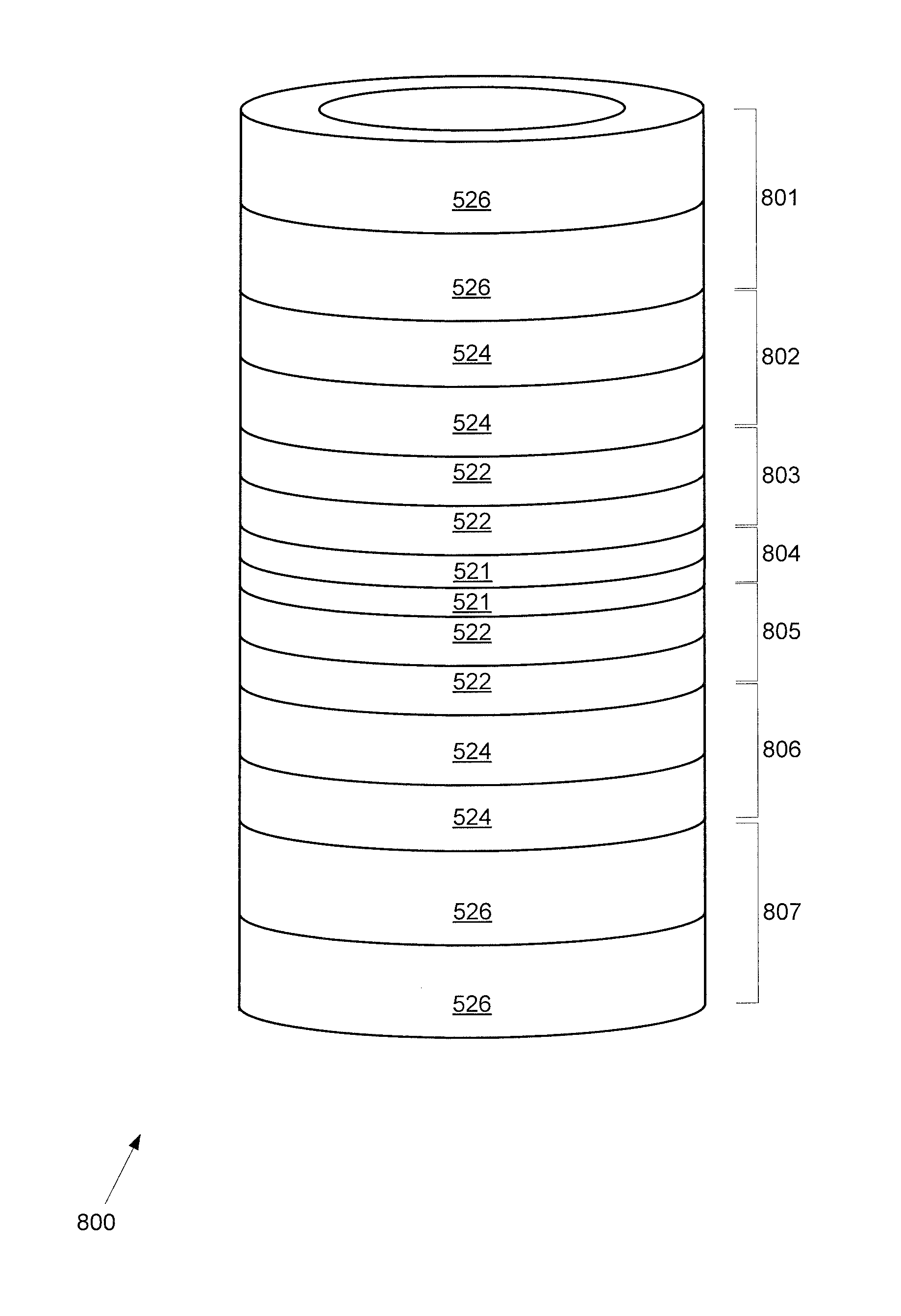
[0057]FIG. 8 shows a second exemplary embodiment of a No-Insulation (NI) Multi-Width (MW) Magnet Construction including a stack 800 of seven DP coils 801-807 wound with bare (no stabilizer) 2G conductor without turn-to-turn insulation. The conductor width is 2.5 mm for the center DP coil 804 and the conductor width increases to 4.0 mm for the top and bottom DP coils 801, 807. As a result, this MW magnet generates more field, for example, approximately 22% more field than its single-width (SW) counterpart. Table 1 presents key magnet parameters of the second embodiment.

TABLE 1Key magnet parametersParametersValuesHTS wire width [mm]2.5-4.0HTS wire thickness [mm]0.08Stabilizern / aWinding i.d; o.d. [mm]40; 50Total height [mm]50# of DP coils7Turn per DP120lc@ 77 K [A]25Charging time constant [s]0.81Center field @ 1 A [mT]16.5Inductance [mH]18.9

[0058]A charge-discharge test was performed in a bath of liquid nitrogen at 77 K. The charge-discharge test compared spa...


PUM

PropertyMeasurementUnit
widthaaaaaaaaaa
widthaaaaaaaaaa
widthaaaaaaaaaa

Abstract

An HTS magnet having a stack of a plurality of double-pancake (DP) coils is disclosed, with each DP coil having a first superconducting coil and a second superconducting coil. The plurality of DP coils have varying widths, with DP coils with the widest widths at the top and bottom of the stack, and DP coils with the narrowest coils located substantially at a midpoint of the stack. The DP coils omit turn-to-turn insulation, or have minimal turn-to-turn insulation.

Description

CROSS-REFERENCE TO RELATED APPLICATIONS[0001]This application claims the benefit of U.S. Provisional Patent Application Ser. No. 61 / 610,071, filed Mar. 13, 2012, entitled “NO-INSULATION MULTI-WIDTH WINDING FOR HIGH TEMPERATURE SUPERCONDUCTING MAGNETS,” which is incorporated by reference herein in its entirety.STATEMENT REGARDING FEDERALLY SPONSORED RESEARCH OR DEVELOPMENT[0002]This invention was made with government support under Grant No. R01 RR015034 awarded by the National Institutes of Health. The government has certain rights in this invention.FIELD OF THE INVENTION[0003]The present invention relates to electro-magnetics, and more particularly, is related to high temperature superconducting magnets.BACKGROUND OF THE INVENTION[0004]High resolution nuclear magnetic resonance (NMR) spectroscopy of liquid samples is a widely utilized analytical technique in diverse applications ranging from pharmaceutical discovery and development of new drugs, to on-line reaction monitoring, to hu...

Claims


Application Information

Patent Timeline
Patent Type & Authority Applications(United States)
IPC IPC(8): H01F6/06H01F41/04
CPCH01F41/048H01F6/06Y10T29/49014
Inventor HAHN, SEUNG-YONGIWASA, YUKIKAZUBASCUNAN, JUANPARK, DONG KEUN
Owner MASSACHUSETTS INST OF TECH
Why Eureka
Try Eureka