High temperature superconducting magnet

Active Publication Date: 2010-04-15
GENERAL ELECTRIC CO
View PDF12 Cites 23 Cited by
  • Summary
  • Abstract
  • Description
  • Claims
  • Application Information

AI Technical Summary

Benefits of technology

[0012]According to yet another embodiment of the invention, a method

Problems solved by technology

The liquid cryogen inventory required to fill the vessel an

Method used


Image

  • High temperature superconducting magnet
  • High temperature superconducting magnet
  • High temperature superconducting magnet

Examples


Embodiment Construction

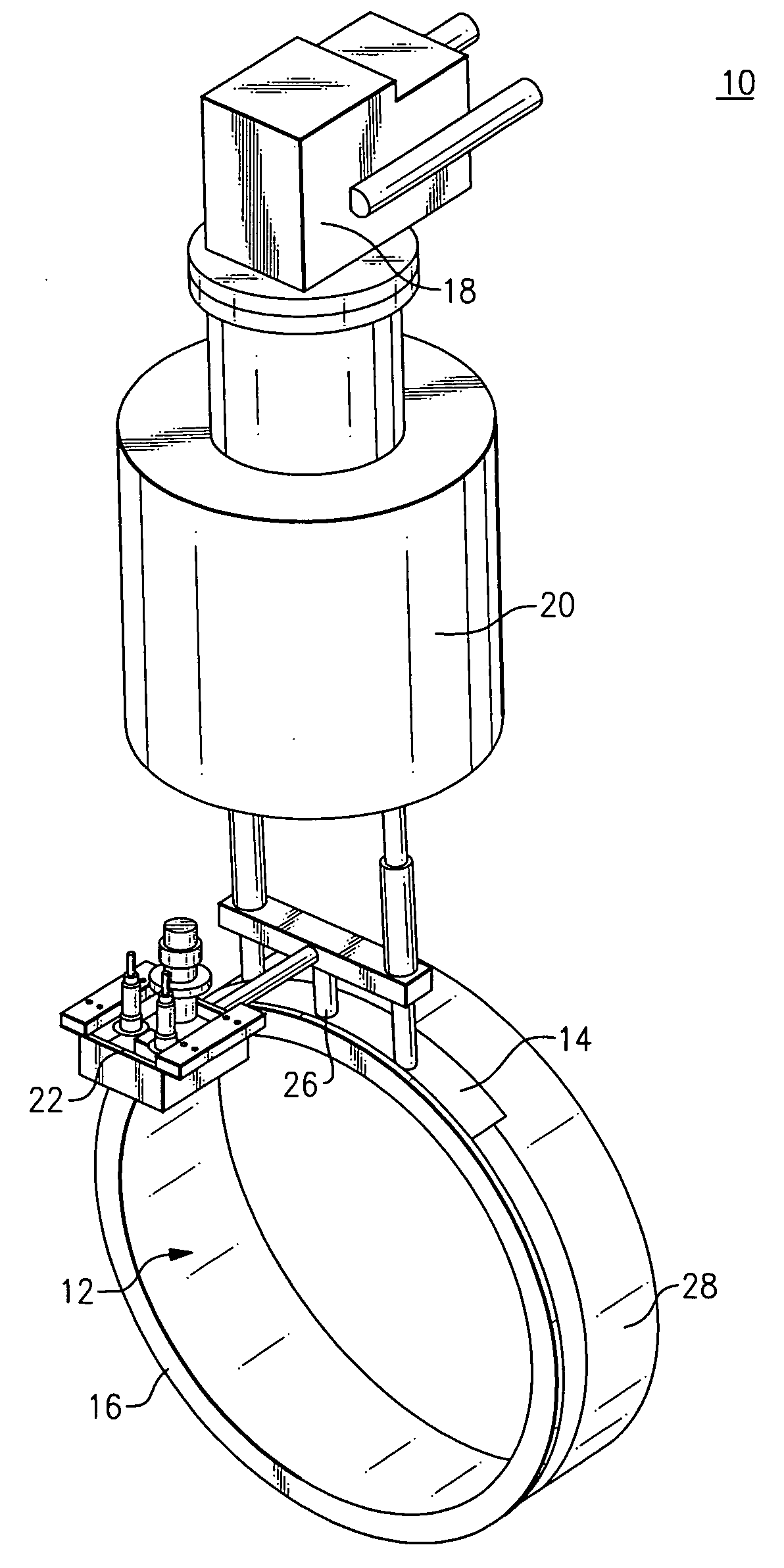
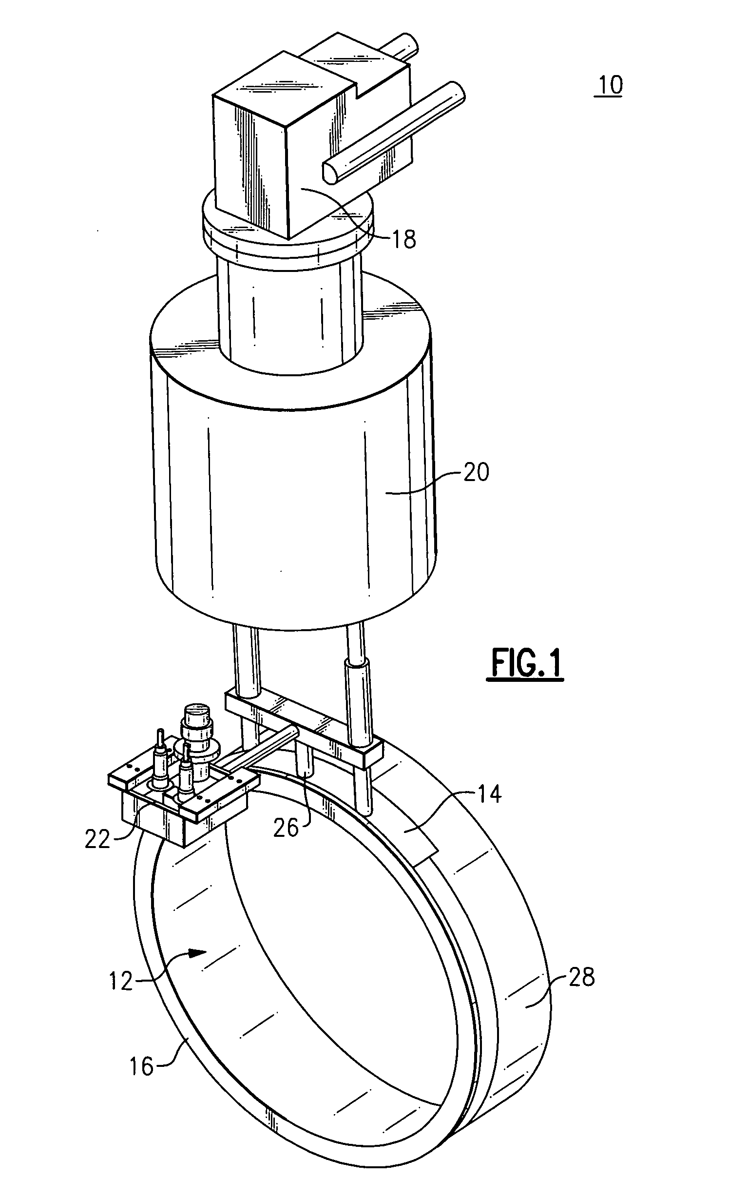
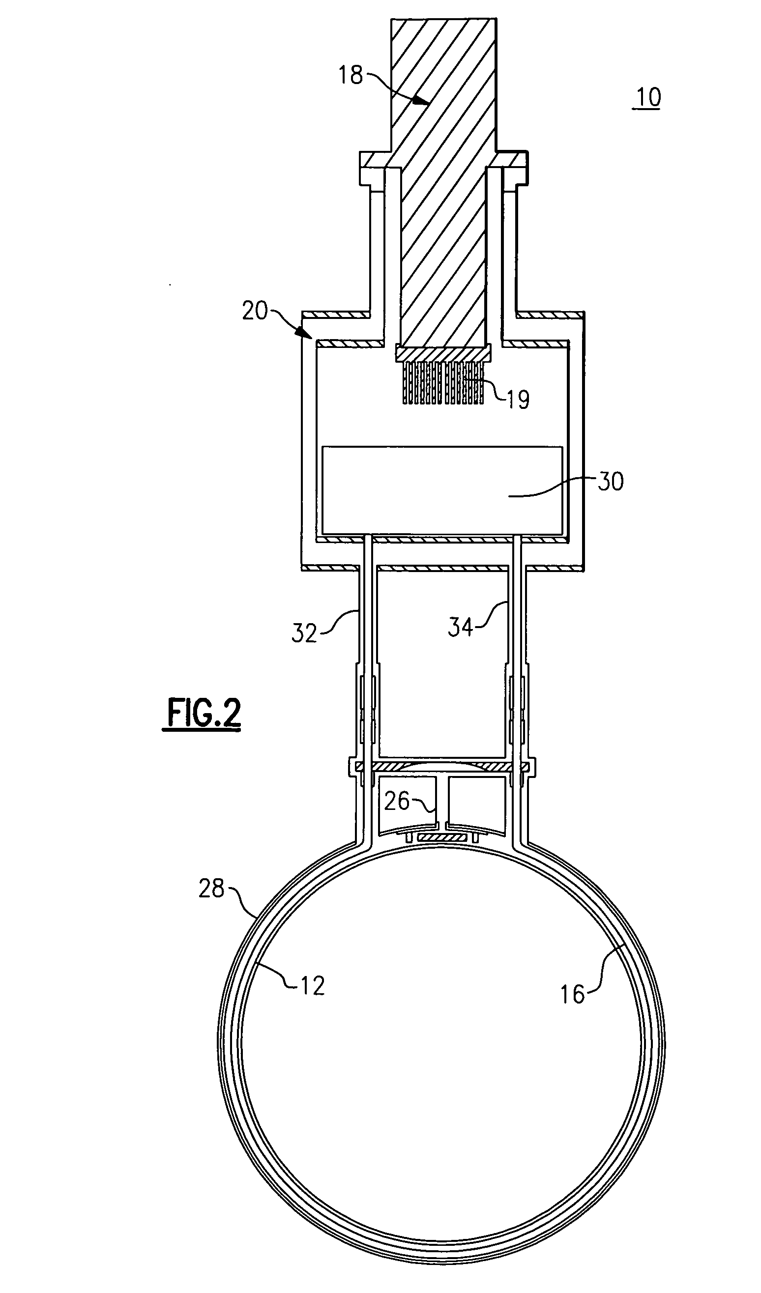
[0022]FIG. 1 is a pictorial diagram illustrating a high temperature superconducting (HTS) magnet assembly 10 according to one embodiment of the invention. In the illustrated example arrangement, the magnet assembly 10 includes an HTS coil 12 having a copper heat exchanger shell 14 that may be a copper foil bonded to the outer surface of the HTS coil 12. The present invention is not so limited however, and it shall be understood that thermally conductive materials known to those skilled in the heat transfer art, other than copper, can be employed in accordance with the principles described herein. Other materials can include, without limitation, aluminum, aluminum alloys, or copper alloys. The copper heat exchanger shell 14 is also bonded to a thermo-siphon cooling coil 16 described in more detail below with reference to FIGS. 2 and 3.

[0023]The thermo-siphon cooling coil 16 is filled with a suitable boiling liquid cryogen such as Neon, for example, to provide indirect thermal conduct...


PUM


Abstract

A high temperature superconducting (HTS) magnet coil disposed within a cryostat is configured with a thermo-siphon cooling system containing a liquid cryogen. The cooling system is configured to indirectly conduction cool the HTS magnet coil by nucleate boiling of the liquid cryogen that is circulated by the thermo-siphon in a cooling tube attached to a heat exchanger bonded to the outside surface of the HTS magnet coil. A supply dewar is configured with a re-condenser cryocooler coldhead to recondense boiloff vapors generated during the nucleate boiling process.

Description

BACKGROUND[0001]The invention relates generally to superconducting magnets, and more particularly to a high temperature superconducting (HTS) magnet implemented via indirect thermal conduction cooling of the HTS coil using a heat exchanger shell that is bonded to a thermo-siphon cooling coil filled with boiling liquid cryogen.[0002]Superconducting magnets are typically immersed in liquid cryogen to implement direct cooling of the superconducting magnet coils. The direct cooling is generally implemented by pool boiling of the liquid cryogen in contact with the magnet coils. The cryogen is typically contained in a large and heavy vessel surrounding the magnet. The liquid cryogen inventory required to fill the vessel and cool the magnet by direct boiling is large and expensive.[0003]It would be advantageous to provide a superconducting magnet that overcomes the size, weight and cost constraints associated with typical superconducting magnets described above.BRIEF DESCRIPTION[0004]Brief...

Claims


Application Information

Patent Timeline
IPC IPC(8): F25B19/00H01F6/04F25D15/00F17C13/00
CPCH01F6/04F17C13/00F25B19/00F25D15/00H02K1/22H02K3/00H02K9/00H02K41/00
Inventor LASKARIS, EVANGELOS TRIFONALEXANDER, JAMES PELLEGRINOSIVASUBRAMANIAM, KIRUBAZHANG, TAO
Owner GENERAL ELECTRIC CO
Why Eureka
Try Eureka