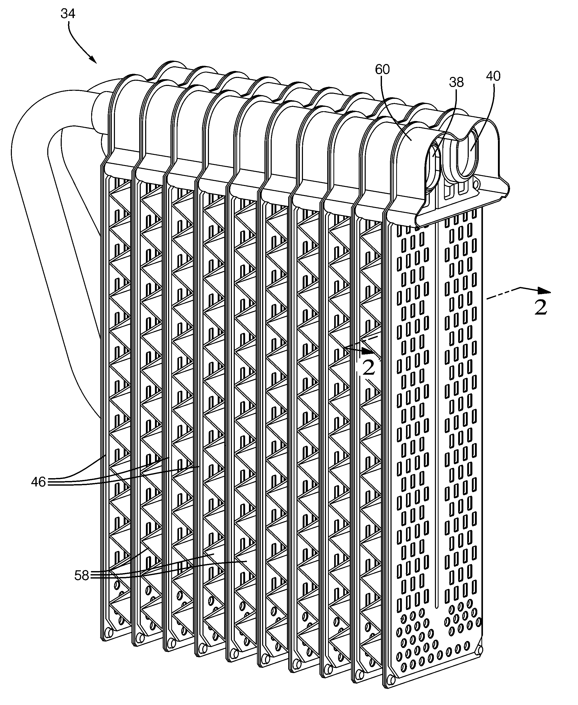
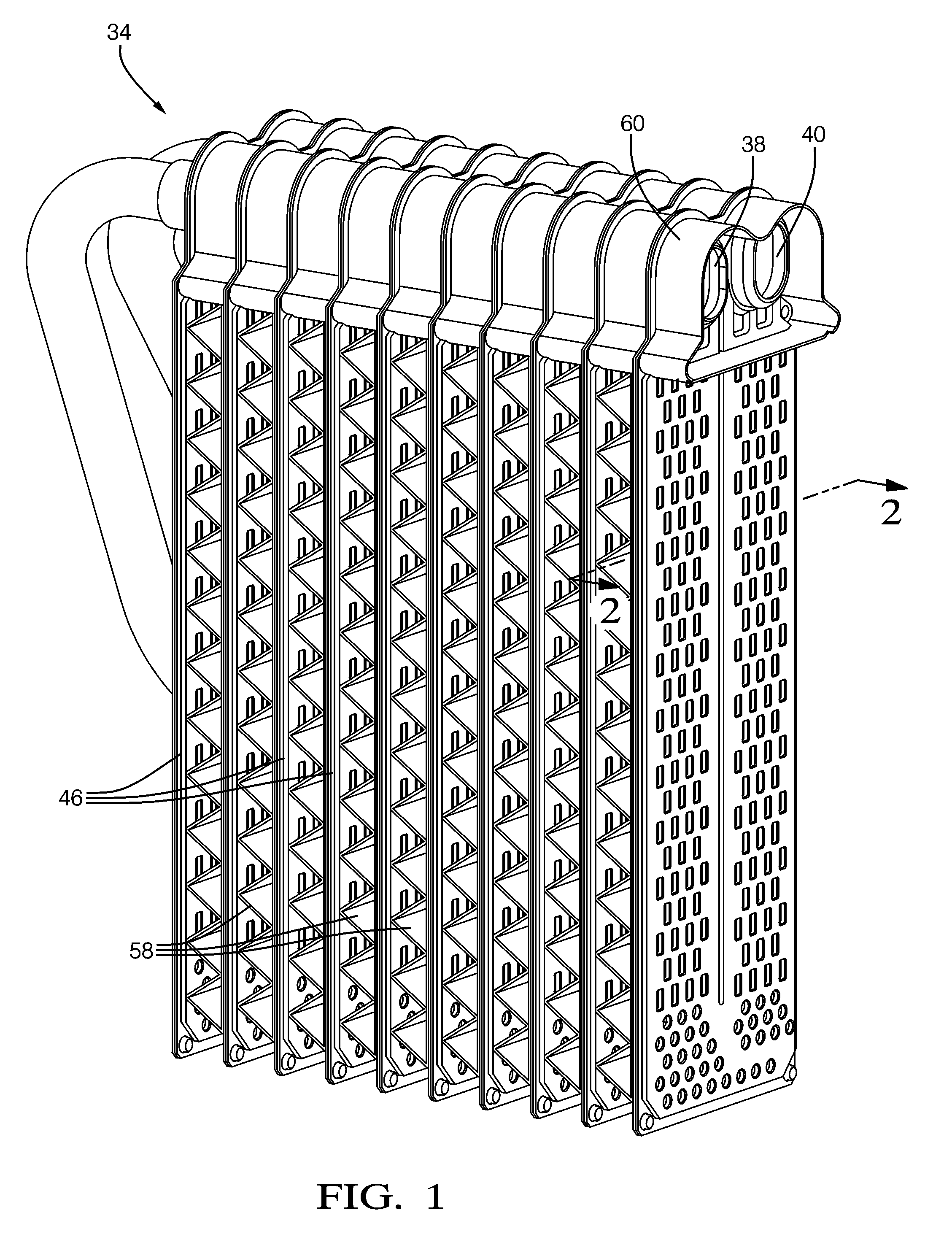
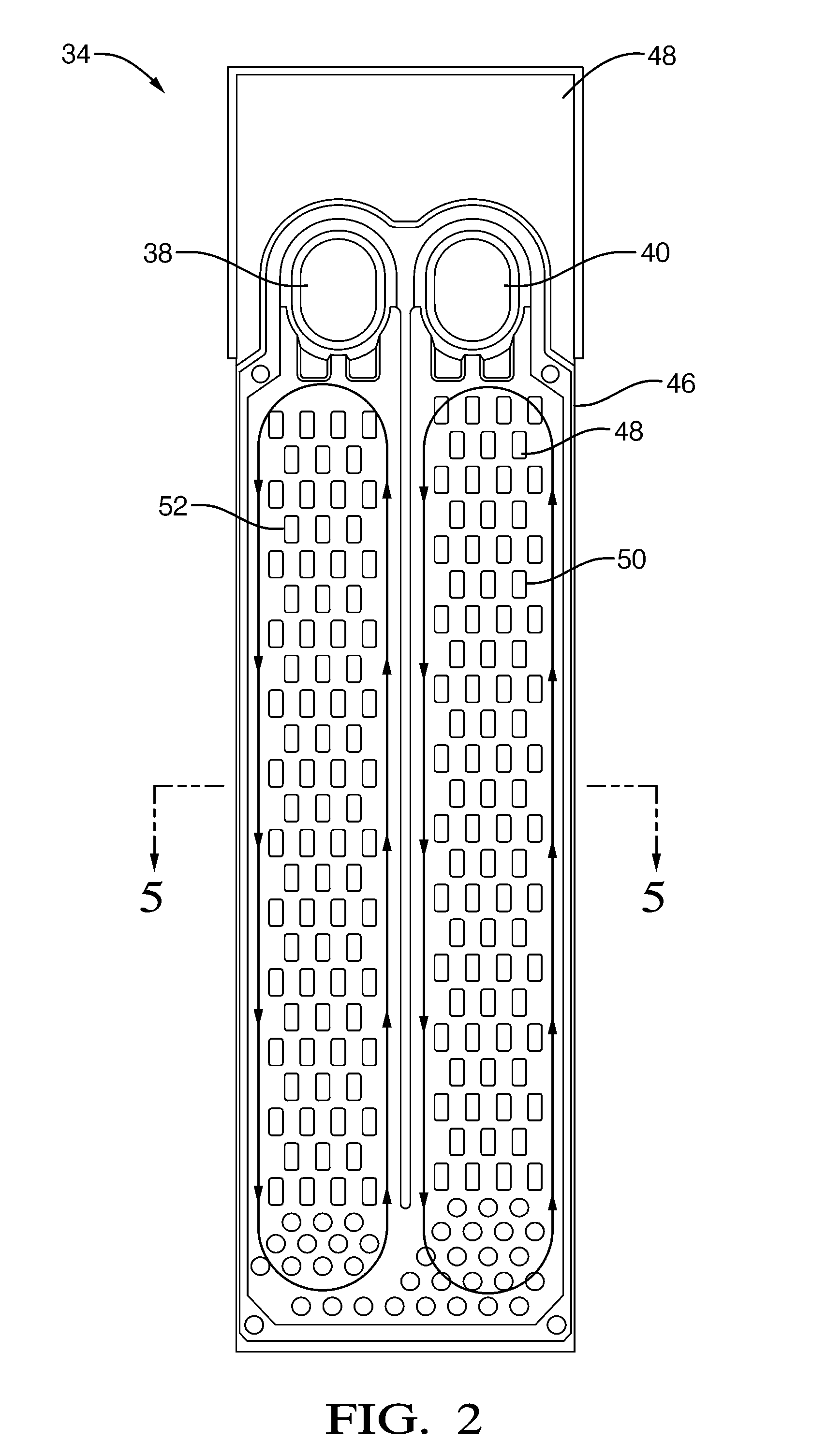
Evaporator Phase Change Thermal Siphon

a technology of phase change and evaporator, which is applied in the direction of indirect heat exchangers, lighting and heating devices, domestic cooling devices, etc., to achieve the effect of less volumous and easy manufacturing

Active Publication Date: 2010-12-16
MAHLE INT GMBH
View PDF13 Cites 40 Cited by
  • Summary
  • Abstract
  • Description
  • Claims
  • Application Information

AI Technical Summary

Benefits of technology

[0008]The air conditioning system provides for an improved passive system for cooling the cabin of a vehicle, both when the engine is running and dormant. It can also be used in a non-vehiclular application. It is less volumous, cheaper and easier to manufacture than the air conditioning systems of the prior art that continue to operate when the engine of the vehicle is dormant. Additionally, because the PCM tank engages one of the manifolds instead of the tubes, it does not obstruct the flow of air. Lastly, it can be integrated into a pre-existing evaporator by engaging a PCM tank to one of the manifolds of the evaporator.

Problems solved by technology

However, the compressor of a traditional air conditioning system runs off the crankshaft of the gasoline engine, and therefore, the gasoline engine continues to operate during those inefficient periods to prevent uncomfortable conditions for the passengers of the vehicle.

Method used


Image

  • Evaporator Phase Change Thermal Siphon
  • Evaporator Phase Change Thermal Siphon
  • Evaporator Phase Change Thermal Siphon

Examples


Embodiment Construction

[0015]Referring to the Figures, wherein like numerals indicate corresponding parts throughout the several views, an air conditioning system 20 is generally shown in FIG. 3. In the exemplary embodiment, the air conditioning system 20 is shown in a vehicle having an engine 22, but the air conditioning system 20 could also be used to cool a building or any other structure. The vehicle of the exemplary embodiment has a first operating mode with the engine 22 of the vehicle running and a second operating mode with the engine 22 of the vehicle dormant. The second operating mode could be a number of different driving conditions, e.g. when the vehicle is coasting or temporarily stopped. The air conditioning system 20 is particularly effective when used in a hybrid-electric vehicle because the air conditioning system 20 of the exemplary embodiment continues to provide cooling for the cabin of the vehicle when the electric motor is driving the vehicle.

[0016]The air conditioning system 20 incl...


PUM


Abstract

An air conditioning system including an evaporator having a manifold and a plurality of tubes extending downward in a vertical direction from the manifold. The evaporator defines at least one PCM tank engaging the manifold for storing a phase change material. When operating in a first operating mode, heat is transferred from the phase change material to the refrigerant to freeze and cool the phase change material. When operating in a second operating mode, heat is transferred from the refrigerant to the frozen phase change material to condense the refrigerant. The condensed refrigerant falls downwardly through the tubes and receives heat from a flow of air to cool the air and evaporate the refrigerant. The evaporated refrigerant rises upwardly back to the low pressure of the cold manifold.

Description

BACKGROUND OF THE INVENTION[0001]1. Field of the Invention[0002]An air conditioning system for cooling the cabin of a vehicle.[0003]2. Description of the Prior Art[0004]Fuel efficiency in vehicles is enhanced by shutting off the gasoline engine during inefficient periods, such as when the vehicle is coasting or temporarily stopped. However, the compressor of a traditional air conditioning system runs off the crankshaft of the gasoline engine, and therefore, the gasoline engine continues to operate during those inefficient periods to prevent uncomfortable conditions for the passengers of the vehicle. It is desirable to have an air conditioning system that continues to operate when the engine is shut off, so that vehicles may shut off their gasoline engine during those inefficient periods.[0005]U.S. Pat. No. 7,156,156, issued to Haller et al. on Jan. 2, 2007 (hereinafter referred to as Haller '156), provides one solution to the problem of the air conditioning system not functioning wh...

Claims


Application Information

Patent Timeline
Patent Type & Authority Applications(United States)
IPC IPC(8): B60H1/32F25B1/00F25B39/02F25D17/02F25D17/04F25B27/00
CPCB60H1/005F25B39/022F25B2400/24F28D1/0341F28D20/02F28D2020/0013F28D2021/0085F28F21/08Y02E60/145Y02E60/14
Inventor WOLFE, IV, EDWARDREYZIN, ILYAKADLE, PRASAD S.BRIGHT, JAMES A.
Owner MAHLE INT GMBH
Why Eureka
Try Eureka