Flex roller-crimper for improved management and termination of cover crops and other plant material

Inactive Publication Date: 2015-08-06
UNIV OF TENNESSEE RES FOUND
View PDF12 Cites 7 Cited by
  • Summary
  • Abstract
  • Description
  • Claims
  • Application Information

AI Technical Summary

Problems solved by technology

However, no-till still possesses issues.
Since the fields are not tilled, soils become compacted, which severely reduces the ability of water to filter through the soil.
In turn, soil compaction reduces crop yield.
Water runoff not only results in unused water, it also moves residual pesticides away from the targeted area and also causes soil erosion.
Also, due to the heavy reliance on herbicides to manage undesirable plants, some of these plants have acquired herbicide tolerances, making them both challenging and costly to manage.
Although cover crops offer many attractive benefits, inefficient methods of termination are slowing their adoption rate.
However, in some scenarios, such as organic farming, herbicides may not be an option.
It i

Method used


Image

  • Flex roller-crimper for improved management and termination of cover crops and other plant material
  • Flex roller-crimper for improved management and termination of cover crops and other plant material
  • Flex roller-crimper for improved management and termination of cover crops and other plant material

Examples


second embodiment

[0032]A second embodiment comprises the strip drum units in the front and the row middle drum units being offset behind the strip units.

third embodiment

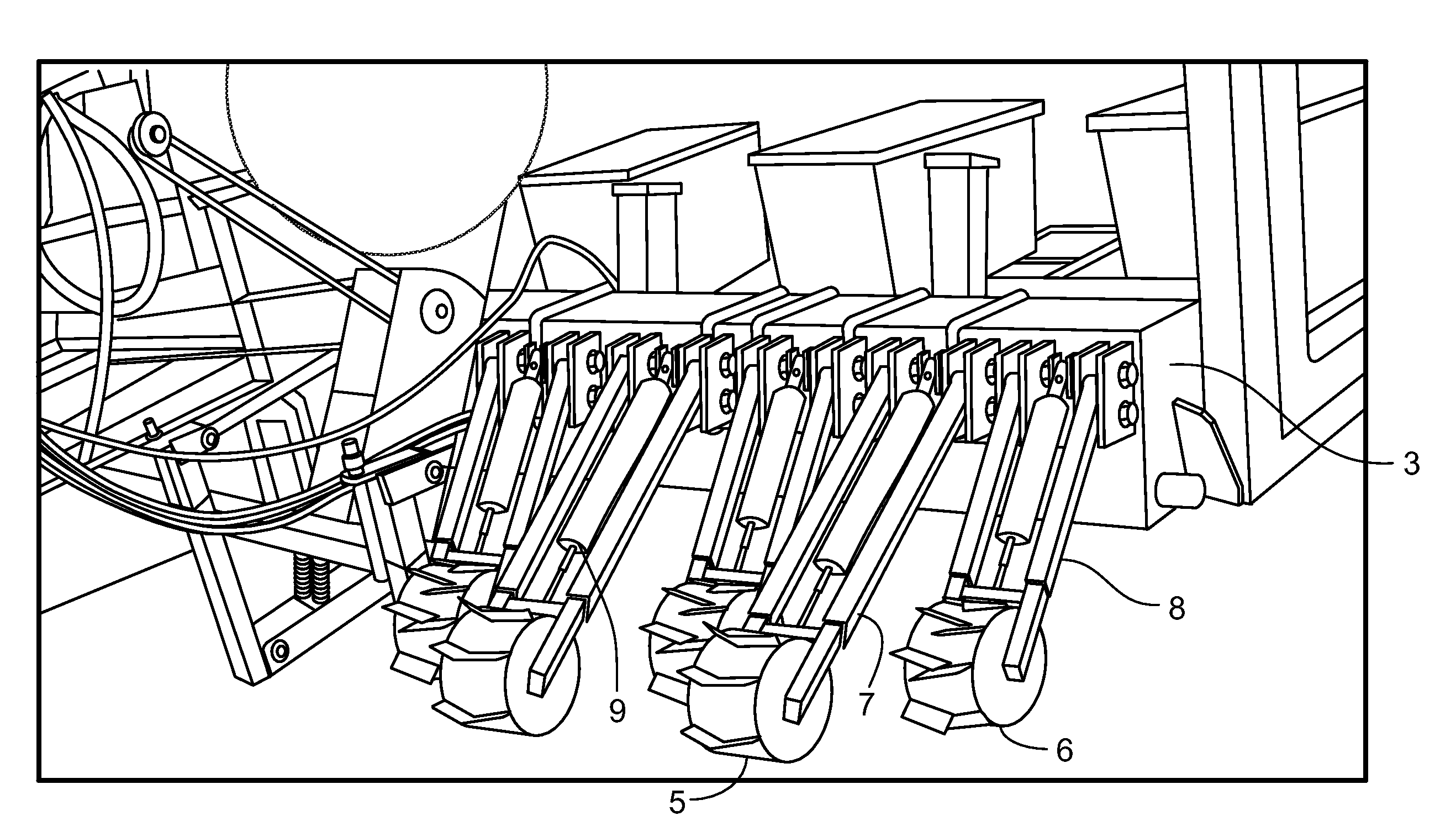
[0033]A third embodiment comprises the flex roller-crimper attached to a frame attached to a planter, the roller-crimper drum units are offset, allowing room for mounting each individual drum while still stretching the entire span of the planter and creating some overlap in the ground coverage of the adjacent drum units, so that the strip drum units are rolling and crimping the planting strip in front of the row middle drum units, which roll and crimp the row middles between the planting units. Each drum unit is attached to the frame of the planter unit by means to both raise and lower each individual drum unit. As understood by a person of ordinary skill in the art, the means by which the drum units may be lifted include pneumatically, hydraulically, fixed, or free floating. Other suitable means are within the scope of this disclosure. It is further understood that any blade pattern or design known in the art may be utilized with the drum unit, including a smooth drum unit design. ...

fourth embodiment

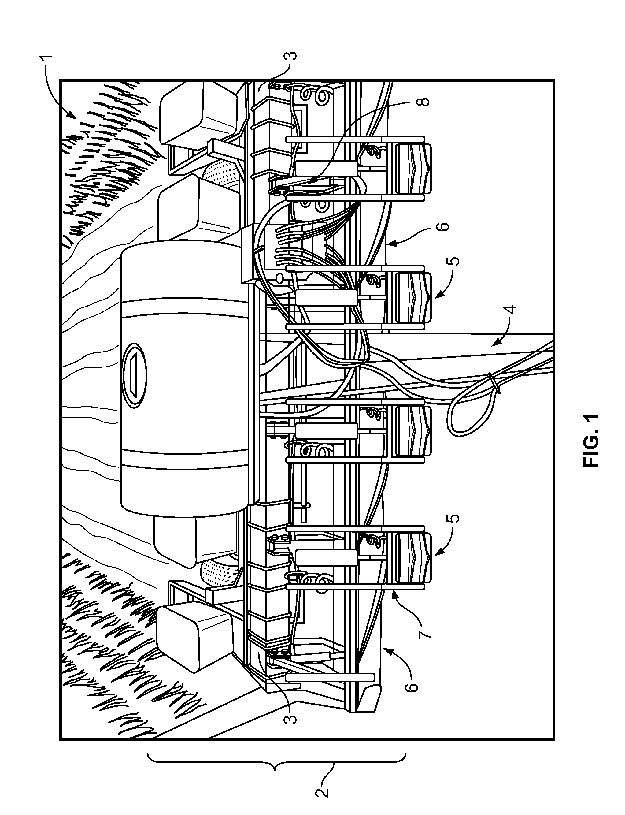
[0034]A fourth embodiment comprises the flex roller crimper wherein the flex roller-crimper comprises a system of drum units with or without fixed blades. The strip drum units are substantially cylindrical and about 6-8″ wide and attached to the frame. The strip drum units roll and crimp cover crop, plant material, or harvest residue in the area in which the cash crop is to be planted. Alternatively, the strip drum units may be lifted so that the row middle drum unit may be used to terminate plant material between the planted rows or rows being prepared for planting.

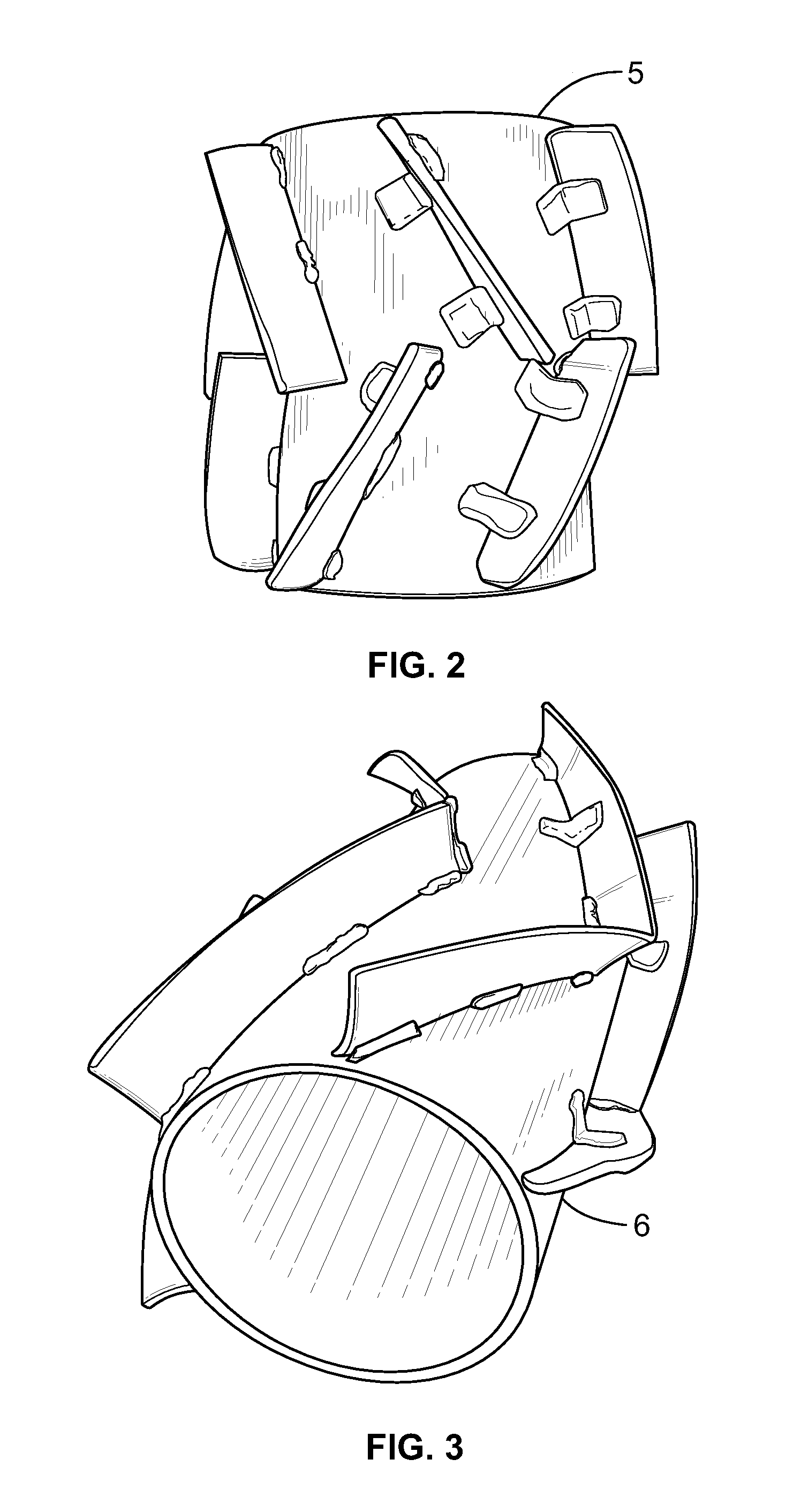
[0035]The row middle drum units are substantially cylindrical and may be about 12″ wide for about a 20″ planting row, about 22″ wide for about a 30″ planting row, or about 30″ wide for about a 38″ planting row. The row middle drum units are also attached to the frame and are offset to the rear of the strip drum units. The drum units nearly uniformly make contact with the ground over the entire span of the frame. Alternat...


PUM


Abstract

Herein is described an agricultural device that can include a frame; and a plurality of roller-crimping devices supported by the frame arranged in at least one row oriented in a direction that is transverse to a direction of travel of the agricultural device. Each of the plurality of roller-crimping devices having an exterior surface configured to at least partially crush stems of residual plant matter, and being individually movably mounted to the frame such that each of the plurality of roller-crimping devices will move at least vertically with respect to the frame when subjected to a temporary increase in resistance caused by an encounter with a non-uniform region in the field.

Description

CROSS-REFERENCE TO RELATED APPLICATIONS[0001]This disclosure claims the benefit of priority to U.S. Provisional Patent Application No. 61 / 936,058 filed Feb. 5, 2014, which is incorporated herein in its entirety.TECHNICAL FIELD[0002]This invention relates to agricultural devices, more directly relating to field preparation for planting or sowing cash crops in no-tillage cropping systems where cover crops, undesirable plants, or plant residue exist by means of an improved modular apparatus for roller-crimping.BACKGROUND OF THE INVENTION[0003]Since the development of “no-till” farming, researchers, consultants, and growers have adopted the practice for its economic and environmental benefits. “No-till” practices consist of managing cash crops with minimal to no tillage used, and inversely relies on herbicides to manage undesirable plants. No-till farming offers many positives, such as reducing erosion, water runoff, as well as fuel, time, and labor costs. However, no-till still possess...

Claims


Application Information

Patent Timeline
IPC IPC(8): A01B61/04A01B39/08
CPCA01B39/08A01B61/046A01B29/00
Inventor BUTLER, SHAWN
Owner UNIV OF TENNESSEE RES FOUND
Why Eureka
Try Eureka