Orthodontic Bracket with Angled, Curved Shutter

a bracket and orthodontic technology, applied in dentistry, medical science, dental tools, etc., can solve the problems of loose archwire within the archwire slot, inability to provide precise tooth positioning, movement or looseness of the archwire within, etc., to facilitate placement and removal of said archwire, facilitate crimping, and facilitate the effect of placement and removal

Active Publication Date: 2015-08-06
ORTHOARM
View PDF2 Cites 19 Cited by
  • Summary
  • Abstract
  • Description
  • Claims
  • Application Information

AI Technical Summary

Benefits of technology

[0023]According to a second embodiment of the invention, there is provided an orthodontic bracket having a body including a bonding base for attachment to the tooth, a lingual vertical slot, a pair of laterally spaced gingival tie wings and a pair of laterally spaced occlusal tie wings, the gingival and occlusal tie wings projecting from a labial surface of the body; an archwire slot extending mesio-distally across the body and between the gingival and occlusal tie wings at opposed medial and distal sides of the body to accommodate an archwire; a locking shutter including at pair of resilient arm members and a lingual guide bar between the resilient arm members, the locking shutter moveable between an open position in which placement and removal of the archwire is facilitated and a closed position in which placement and removal of the archwire is inhibited; first and second tracks formed on each of first and second outer lateral surfaces of the body, extending from the occlusal tie wings across the archwire slot and into the gingival tie wings; the first and second tracks sized and otherwise dimensioned to receive the pair of resilient arm members therein; wherein the first and second tracks extend in a substantially occlusal-gingival direction, angled lingually by an angle Θ with respect to a plane parallel to a vertical that is perpendicular to the occlusal plane on the outer lateral surfaces such that the first and second tracks.
[0024]According to one aspect of this second embodiment, the first and second tracks start in the reverse direction, from a more labial position on the gingival aspect of the bracket and extend approximately parallel to one another, and diagonally across the archwire slot and into the latter aspects of the occlusal wings at a distance labial to the base of the archwire slot so that an archwire can be secured in the archwire slot as the pair of resilient arms slides in the tracks.
[0025]According to another aspect of this second embodiment, the centrally located guide bar starts parallel to the outer track arms then jogs in a approximately L-shaped pattern towards the lingual such that the gingival aspect of the guide bar end is located in a more lingual position than the outer track arms.
[0026]According to a third embodiment of the invention, an orthodontic bracket with a body has a bonding base for attachment to the tooth, a pair of laterally spaced gingival tie wings and a pair of laterally spaced occlusal tie wings. The gingival and occlusal tie wings project from a labial surface of the body. An archwire slot extends mesiodistally across the body and between the gingival and occlusal tie wings at opposed medial and distal sides of the body to accommodate an archwire. A locking shutter having two resilient arm members that are curved in a labial-lingual direction with a shutter protrusion that is also curved extending from each of resilient arm members and a centrally located and curved guide bar. The resilient arms and the lingual guide bar are curved in a convex shape relative to a base of the archwire slot, and the tracks are correspondingly curved to receive the curved resilient arms. The locking shutter is moveable between an open position in which

Problems solved by technology

One of the problems associated with this passive, straight clip design is that the archwire is loose within the archwire slot and does not fully provide precise tooth positioning.
One problem associated with the Bryant et al. disclosure is that the shim prevents movement of the archwire out of the archwire slot, but, depending on the size of the archwire being used, the shi

Method used


Image

  • Orthodontic Bracket with Angled, Curved Shutter
  • Orthodontic Bracket with Angled, Curved Shutter
  • Orthodontic Bracket with Angled, Curved Shutter

Examples


Embodiment Construction

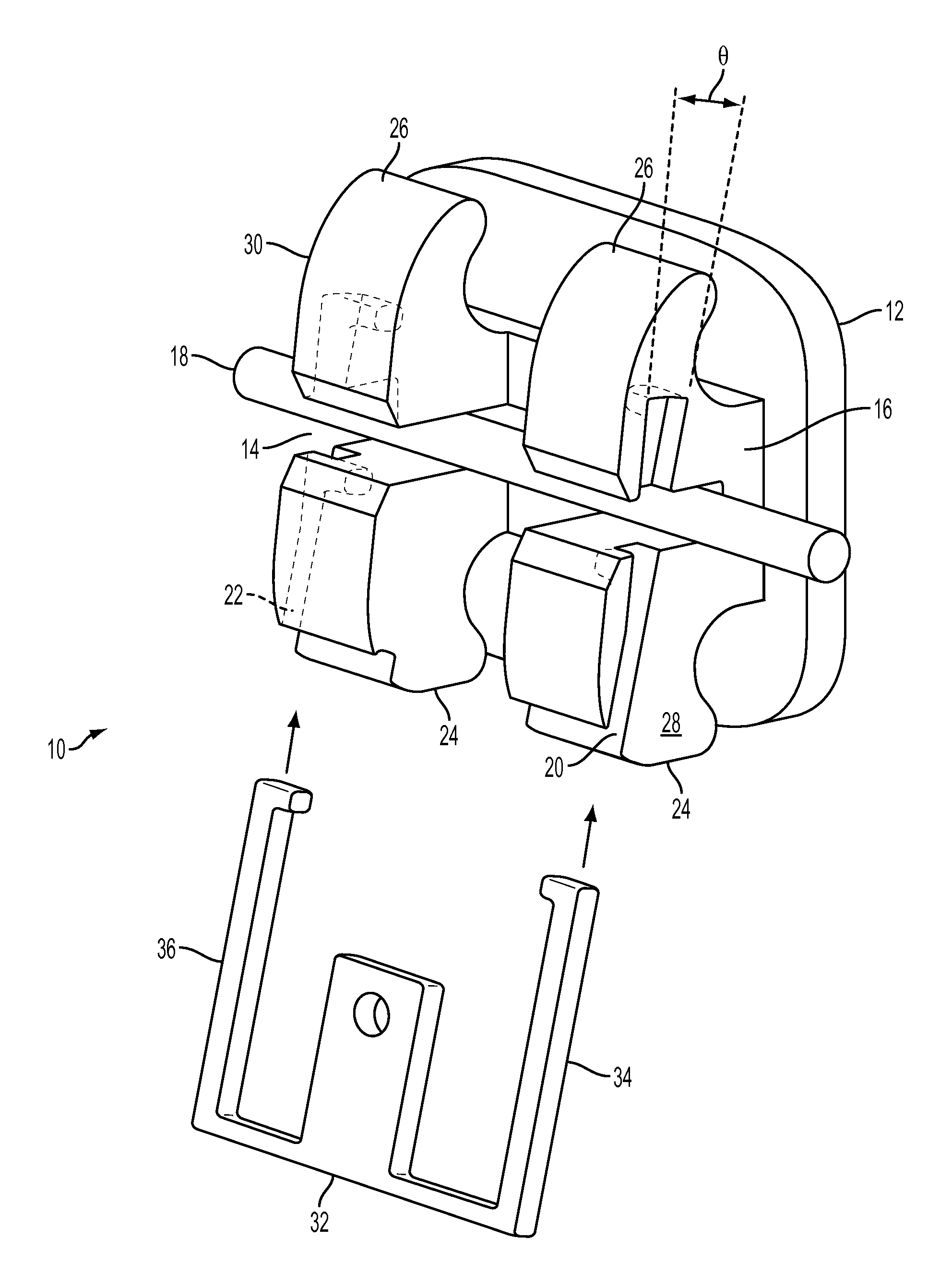
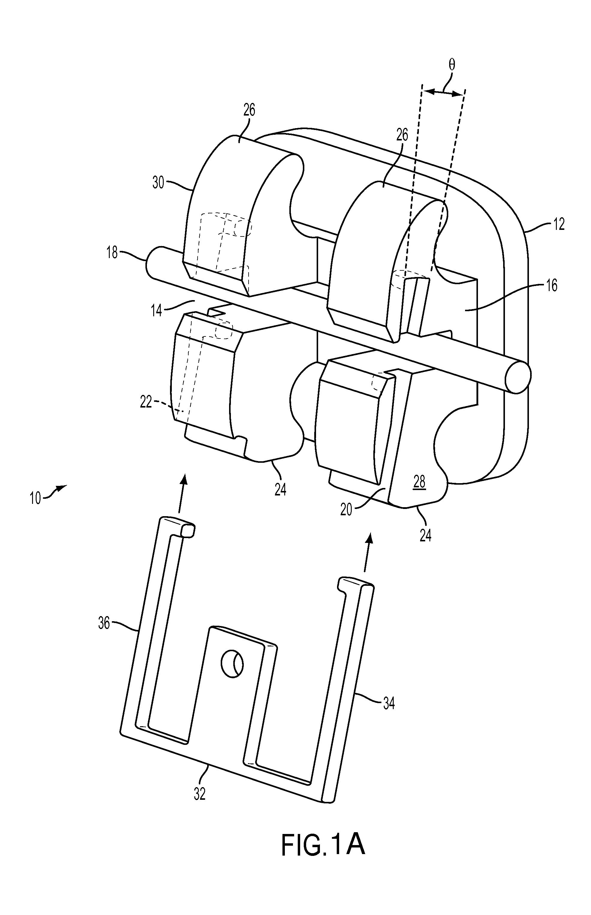
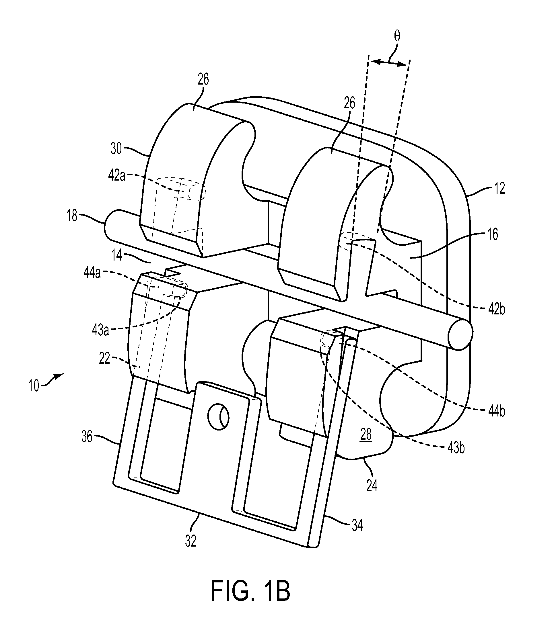
[0050]Referring now to the FIGS. 1A to 1C, there is shown one embodiment of the self-ligating bracket according to the invention in which an orthodontic bracket 10 is provided having a bonding pad 12 for attachment to a tooth (not shown). An archwire slot 14 extends in a substantially mesiodistal direction across the body 16 of the bracket 10 with an open labial aspect to receive an archwire 18. Occlusal tie wings 24 and gingival tie wings 26 are provided on opposed sides of the body 16. These elements are not described in more detail as their purpose and functioning is generally known in the art.

[0051]In this embodiment of the invention, two outer tracks 20 and 22 extend in a substantially occlusal-gingival direction, angled gingivally by angle Θ (shown in FIGS. 1A to 2B, and more clearly in FIG. 3) with respect to a plane parallel with the vertical plane of a tooth on the outer lateral surfaces 28, 30 of the bracket 10. One outer track 20 runs along the mesial surface 28, and the ...


PUM


Abstract

An orthodontic bracket that having a clip angulated toward the lingual direction in a diagonal orientation for active seating of archwires. The bracket having a lingual vertical slot, a pair of gingival tie wings and a pair of occlusal tie wings. An archwire slot extending mesiodistally across the body. A locking shutter with a pair of resilient arms connected by a guide bar and moveable between an open position allowing placement of the archwire and a closed position inhibiting removal of the archwire. A pair of tracks on each of the outer lateral surfaces of the body, extending from the occlusal tie wings and into the gingival tie wings. The tracks dimensioned to receive the resilient arms therein. The tracks extend in a substantially occlusal-gingival direction, angled lingually by an angle Θ with respect to a plane parallel to a vertical that is perpendicular to the occlusal plane.

Description

RELATED APPLICATIONS[0001]This application is a continuation-in-part of U.S. patent application Ser. No. 13 / 852,351 filed Mar. 28, 2013, which claims priority to U.S. Provisional Application No. 61 / 616,462 filed Mar. 28, 2012; the contents of all of which are herein expressly incorporated by reference.FIELD OF THE INVENTION[0002]The present invention relates to the field of orthodontic brackets, and more particularly to a self-ligating bracket having active archwire retention.BACKGROUND OF THE INVENTION[0003]Orthodontic treatment is effected by fixing small appliances often referred to as orthodontic brackets to a patient's teeth in an appropriate manner so as to correct malaligned teeth by applying an external force thereto through an archwire extending between the generally fixed orthodontic brackets. Directions mesial and distal mean generally left to right. Labial is the front surface, while lingual is defined as anything toward the direction of the tongue and it thereby stands ...

Claims


Application Information

Patent Timeline
IPC IPC(8): A61C7/28A61C7/30
CPCA61C7/30A61C7/287
Inventor VOUDOURIS, JOHN
Owner ORTHOARM
Why Eureka
Try Eureka