Vehicle lamp

a technology for lamps and vehicles, applied in the field of lamps for vehicles, can solve the problems of stray light and stray light, and achieve the effect of reducing glar

Active Publication Date: 2015-08-06
KOITO MFG CO LTD
View PDF4 Cites 18 Cited by
  • Summary
  • Abstract
  • Description
  • Claims
  • Application Information

AI Technical Summary

Benefits of technology

[0021]According to the exemplary embodiments of the invent...

Problems solved by technology

However, in the vehicle lighting device mentioned above, stray light may occur due to reflection from various components provided in the vehicle lighting device and stray light may occur due to malfunction of t...

Method used


Image

  • Vehicle lamp
  • Vehicle lamp
  • Vehicle lamp

Examples


first embodiment

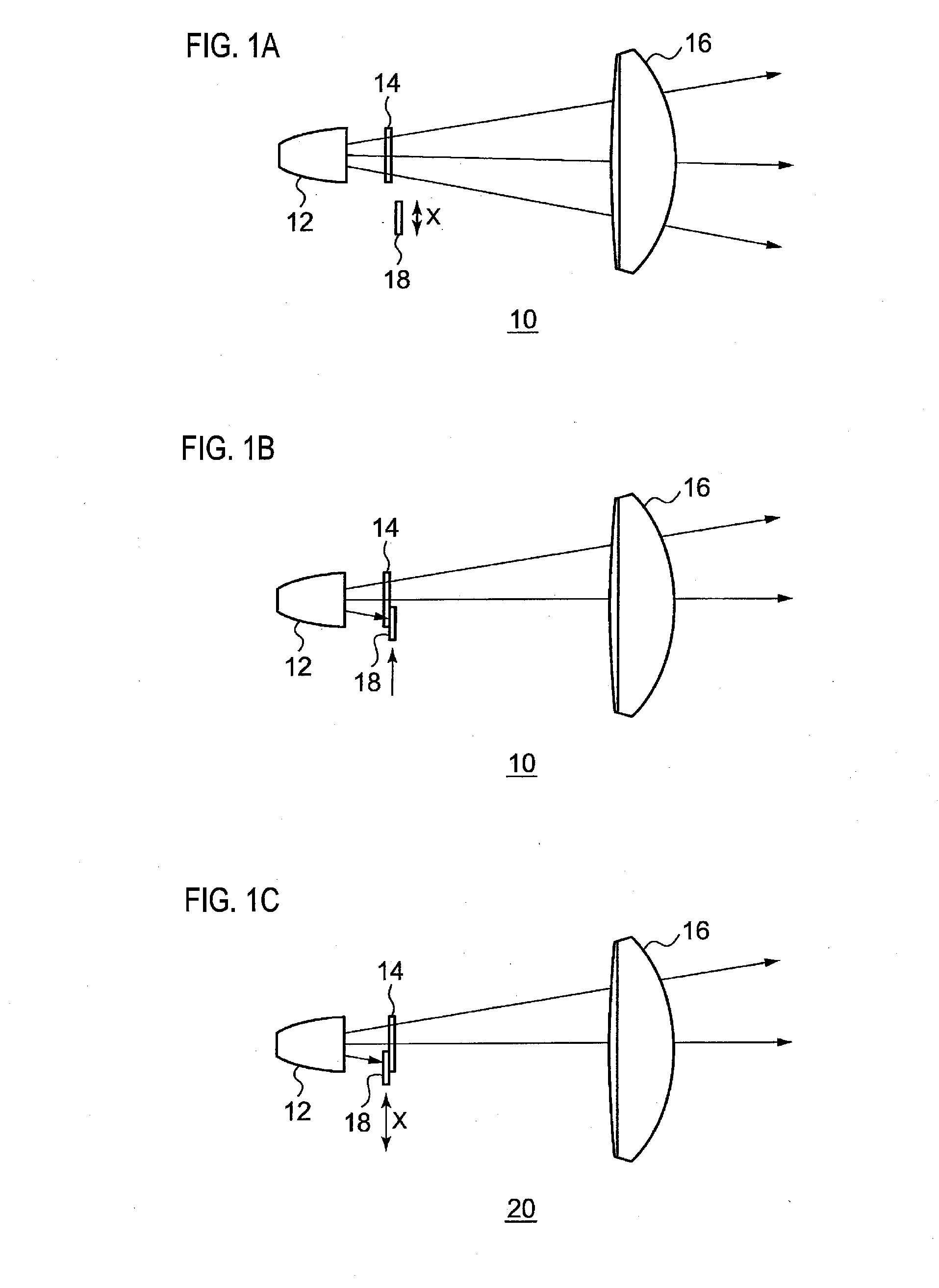
[0034]FIG. 1A is a side view schematically illustrating a vehicle lamp according to a first embodiment, FIG. 1B is a side view illustrating a state in which a light blocking member in the vehicle lamp illustrated in FIG. 1A has moved to a light blocking position, and FIG. 1C is a side view schematically illustrating a modified example of a vehicle lamp according to the first embodiment.

[0035]A vehicle lamp 10 includes a light source 12, a 2D image forming device 14 that forms a brightness image using light emitted from the light source 12, a projection lens 16 serving as an example of an optical projection system that projects the brightness image forward, and a light blocking member 18 that is disposed on the path of light emitted from the light source 12, through the 2D image forming device 14, and onward toward the projection lens 16, and blocks at least some of the light.

[0036]Various devices applied to vehicle lamps may be employed for the light source 12. Examples thereof incl...

second embodiment

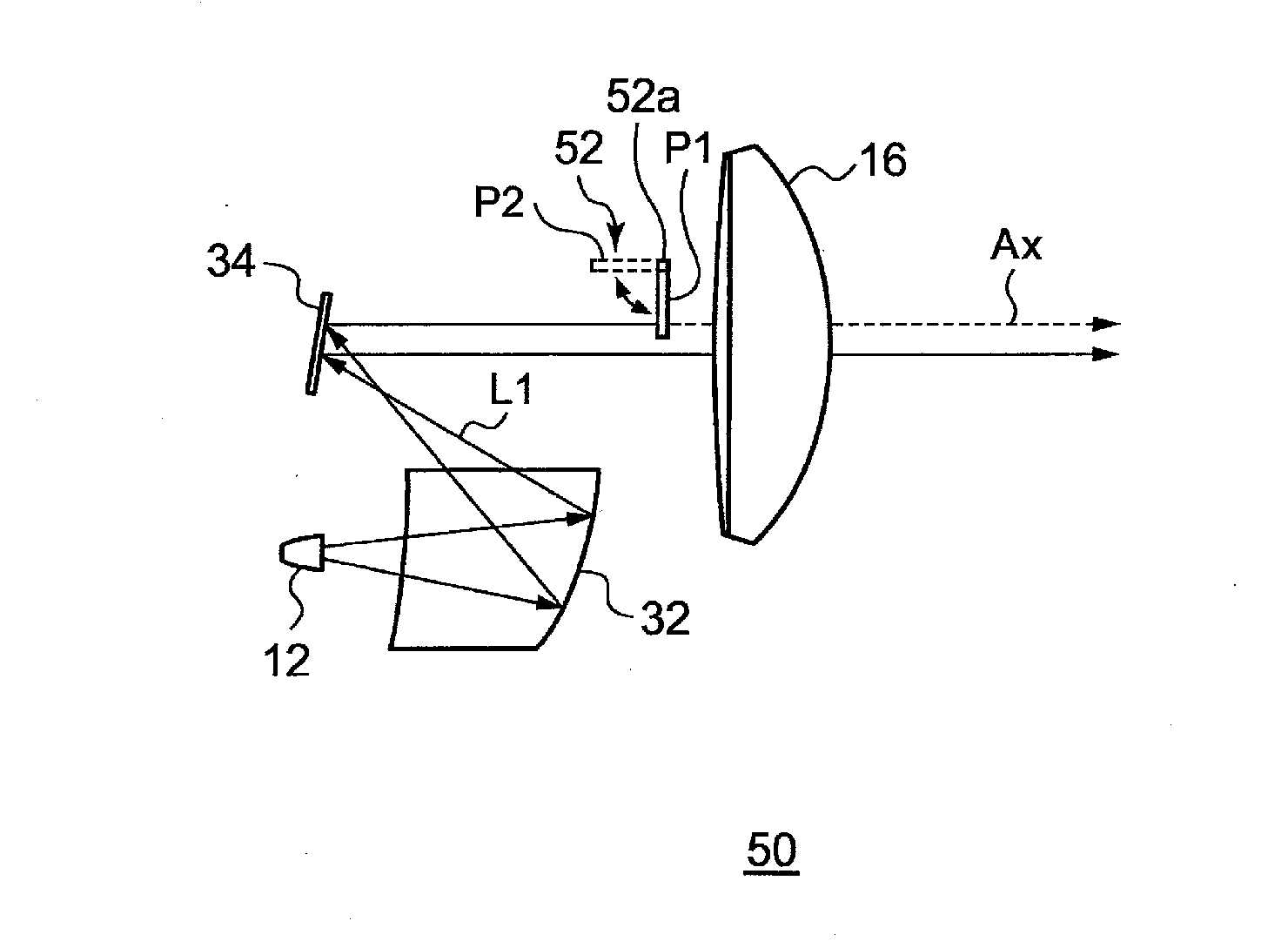
[0046]FIG. 4A is a side view schematically illustrating a vehicle lamp according to a second embodiment, FIG. 4B is a side view illustrating a state in which a light blocking member of the vehicle lamp illustrated in FIG. 4A has been moved to a light blocking position, and FIG. 4C is a side view schematically illustrating a modified example of a vehicle lamp according to the second embodiment.

[0047]A vehicle lamp 30 includes a light source 12, a reflector 32 that reflects light so as to concentrate light emitted from the light source 12, a 2D image forming device 34 that forms a brightness image with the light reflected by the reflector 32, a projection lens 16 that projects the brightness image forward, and a light blocking member 18 disposed on the path of light emitted from the light source 12, through the 2D image forming device 34, and onward toward the projection lens 16, and blocks at least some of the light.

[0048]The 2D image forming device 34 is a reflection type device tha...


PUM


Abstract

A vehicle lamp includes a 2D image forming device configured to form a brightness image using light emitted from a light source, an optical projection system configured to project the brightness image forward, and a light blocking member disposed on a path of light emitted from the light source through the 2D image forming device and onward toward the optical projection system, and configured to block at least a portion of the light.

Description

CROSS-REFERENCE TO RELATED APPLICATION[0001]The present application claims priority from Japanese Patent Application No. 2014-018767 filed on Feb. 3, 2014, the entire content of which is incorporated herein by reference.BACKGROUND OF INVENTION[0002]1. Field of Invention[0003]The present disclosure relates to a vehicle lamp.[0004]2. Related Art[0005]Proposals exist for a vehicle lighting device that forms a desired light distribution pattern by reflecting light emitted from a light source, using a reflection direction converter disposed with plural reflection elements in a matrix formation, and passing the reflected light through a lens (see Patent Document 1). Such a vehicle lighting device can form plural shapes of light distribution pattern by controlling some of multi-arrayed reflection elements so that some of the light emitted from the light source is reflected in a direction other than toward the lens.PRIOR ART LITERATUREPatent Document[0006]Patent Document 1: JP-A-9-104288[00...

Claims


Application Information

Patent Timeline
IPC IPC(8): F21S8/10F21W107/10
CPCF21S48/125F21W2101/10F21S48/1721F21S48/145F21S41/255F21S41/36F21S41/43F21S41/645F21S41/663F21S41/675F21S41/686F21S41/689F21S41/143F21S41/321F21S41/365F21S41/635
Inventor YAGI, TAKAYUKIYAMAMURA, SATOSHI
Owner KOITO MFG CO LTD
Why Eureka
Try Eureka