Anti-glare film, manufacturing method for same, polarizing plate and image display device

An anti-glare film and coating technology, which is applied in polarizing elements, chemical instruments and methods, nonlinear optics, etc., can solve the problem of particle agglomeration state of amorphous agglomerates of anti-glare layers, reduced visibility of display images, etc. Inability to adequately suppress problems such as fading

Active Publication Date: 2012-11-14
DAI NIPPON PRINTING CO LTD
View PDF13 Cites 6 Cited by
  • Summary
  • Abstract
  • Description
  • Claims
  • Application Information

AI Technical Summary

Problems solved by technology

[0013] However, Patent Document 6 does not study the aggregation state of the particles of the amorphous aggregates contained in the anti-glare layer. aggregate
Therefore, in the anti-glare film described in Patent Document 6, a large nu

Method used


Image

  • Anti-glare film, manufacturing method for same, polarizing plate and image display device
  • Anti-glare film, manufacturing method for same, polarizing plate and image display device
  • Anti-glare film, manufacturing method for same, polarizing plate and image display device

Examples


Embodiment 1

[0209] First, triacetyl cellulose (manufactured by Fujifilm Co., Ltd., thickness 80 μm) was prepared as a translucent substrate.

[0210] Next, as a radiation-curable adhesive, a mixture of pentaerythritol triacrylate (PETA), dipentaerythritol hexaacrylate (DPHA) and polymethyl methacrylate (PMMA) (mass ratio; PETA / DPHA / PMMA) was used. =86 / 5 / 9) (refractive index 1.51), as photopolymerization initiator, use 1-hydroxyl-cyclohexyl-phenyl-ketone: Irgacure 184 (manufactured by BASF company) (relative to adhesive solid content 100 mass 5 parts by mass), with respect to 100 parts by mass of the radiation-curable adhesive, high-crosslinked polystyrene particles (refractive index 1.59, average particle diameter 4.0 μm) 12 as fine particles (A) were contained therein. Parts by mass contained 20 parts by mass of talc particles (refractive index: 1.57, average particle diameter D50: 0.8 μm) as a layered inorganic compound with respect to 100 parts by mass of the radiation-curable adhesive...

Embodiment 2~7、 comparative example 1~9

[0213] (Examples 2-7, Comparative Examples 1-9, Reference Example 1)

[0214] The anti-glare film was produced in the same manner as in Example 1 except that the thicknesses of the components added to the coating liquid and the formed diffusion layer were shown in Table 1.

[0215] 【Table 1】

[0216]

[0217] In Table 1, the details of the symbols shown in the microparticles (A), organic microparticles (B), radiation-curable adhesives, and layered inorganic compounds are as follows. In addition, in Table 1, content of microparticles|fine-particles (A), organic microparticles (B), and layered inorganic compound shows content (mass part) with respect to 100 mass parts of radiation-curable adhesives.

[0218] (Particle A)

[0219] A: Highly cross-linked polystyrene particles (refractive index 1.59, average particle diameter 4.0 μm, manufactured by Soken Chemical Co., Ltd.)

[0220] B: Highly cross-linked acrylic-polystyrene particles (refractive index 1.57, average particle...


PUM

PropertyMeasurementUnit
The average thicknessaaaaaaaaaa
The average particle sizeaaaaaaaaaa

Abstract

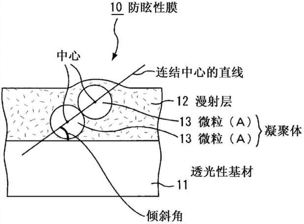
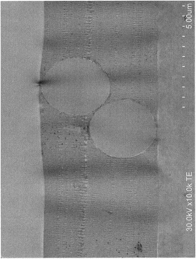
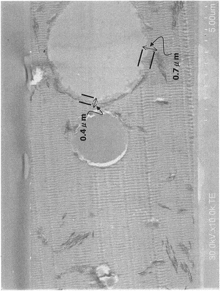
Provided is an anti-glare film that has excellent anti-glare properties, can sufficiently suppress discoloration, has high contrast, and can prevent surface glare. The anti-glare film is provided with a light-permeable base material and a diffusion layer that has an uneven pattern on the surface and is formed on at least one surface of the light-permeable base material. The anti-glare film is characterized in that a coating solution, which includes a radiation-curable binder that comprises, as necessary components, microparticles (A) and a (meth)acrylate monomer, is coated onto at least one surface of the light-permeable base material, is dried to form a coating film, and then cured to form the diffusion layer, and in that 50% of the microparticles (A) within the diffusion layer form an agglomerated pair in which the line extending through the centers of both microparticles forms an angle of inclination relative to the surface of the above light-permeable surface.

Description

technical field [0001] The present invention relates to an antiglare film, a method for producing the antiglare film, a polarizing plate, and an image display device. Background technique [0002] In image display devices such as cathode ray tube display (CRT), liquid crystal display (LCD), plasma display (PDP), electroluminescent display (ELD), electronic paper, etc., usually, a useful Optical layered body for anti-reflection. Such an optical layered body for antireflection suppresses reflection of an image by diffusion or interference of light, and reduces reflectance. [0003] As one of the optical layered products for antireflection, an antiglare film in which an antiglare layer having a concavo-convex shape is formed on the surface of a transparent substrate is known. The anti-glare film diffuses external light by utilizing the uneven shape of the surface, thereby preventing a decrease in visibility. In addition, since such an antiglare film is generally provided on ...

Claims


Application Information

Patent Timeline
IPC IPC(8): G02B5/02B32B27/20B32B27/30G02B1/10G02B5/30G02F1/1335G02B1/11G02B1/14
CPCG02B5/0278G02B5/0242G02B5/0294G02B1/10G02B5/02G02B5/30G02F1/1335
Inventor 儿玉崇本田诚铃木裕子
Owner DAI NIPPON PRINTING CO LTD
Why Eureka
Try Eureka