Anti-glare film, polarizer, liquid-crystal panel, and image display device

a technology of liquid crystal panels and films, applied in the direction of instruments, polarising elements, coatings, etc., can solve the problems of image blur, reduced dark room contrast, light scattering, etc., and achieve the effect of suppressing glare, low internal haze, and low total haz

Active Publication Date: 2016-08-25
DAI NIPPON PRINTING CO LTD
View PDF0 Cites 7 Cited by
  • Summary
  • Abstract
  • Description
  • Claims
  • Application Information

AI Technical Summary

Benefits of technology

[0010]The present invention was accomplished to solve the above-described problems. That is, the present invention is aimed at providing an antiglare film which is capable of suppressing glare and has a low total haze and a low internal haze; an antiglare film which has a low total haze and a low internal haze and is capable of suppressing glare and of blurring the contour of a reflected image; a polarizing plate; a liquid crystal panel; and an image display apparatus.

Problems solved by technology

However, there is a fear that image light scatters due to the concavo-convex surface of an antiglare layer, whereby so-called glare is generated, in a case in which such an antiglare film is placed on a surface of an image display apparatus.
Because enhancement of the total haze or internal haze of the antiglare film results in reduction in luminance and light transmittance, it is impossible to adopt, as means for suppressing glare, means of enhancing the internal haze of the antiglare film as described above in the super-high-definition image display apparatus.
There is a fear that the enhancement of the internal haze of the antiglare film results in diffusion of image light in the antiglare film, whereby part of image light becomes stray light.
As a result, there is also a fear that a dark room contrast is reduced, and an image blurs.

Method used


Image

  • Anti-glare film, polarizer, liquid-crystal panel, and image display device
  • Anti-glare film, polarizer, liquid-crystal panel, and image display device
  • Anti-glare film, polarizer, liquid-crystal panel, and image display device

Examples


first embodiment

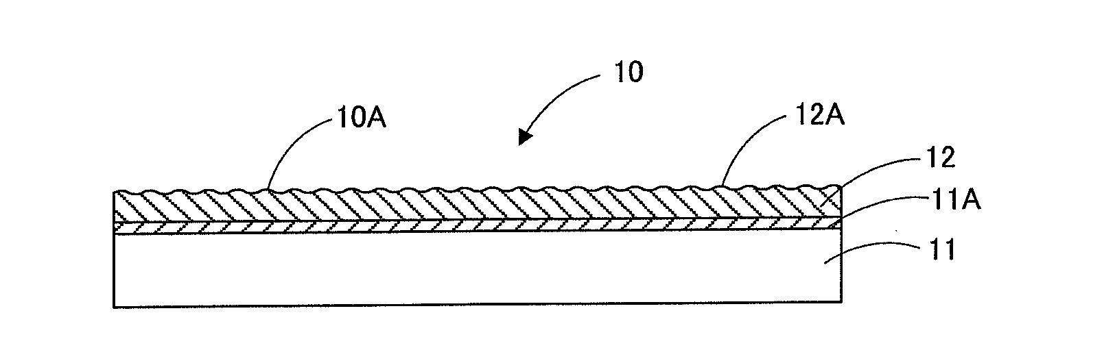
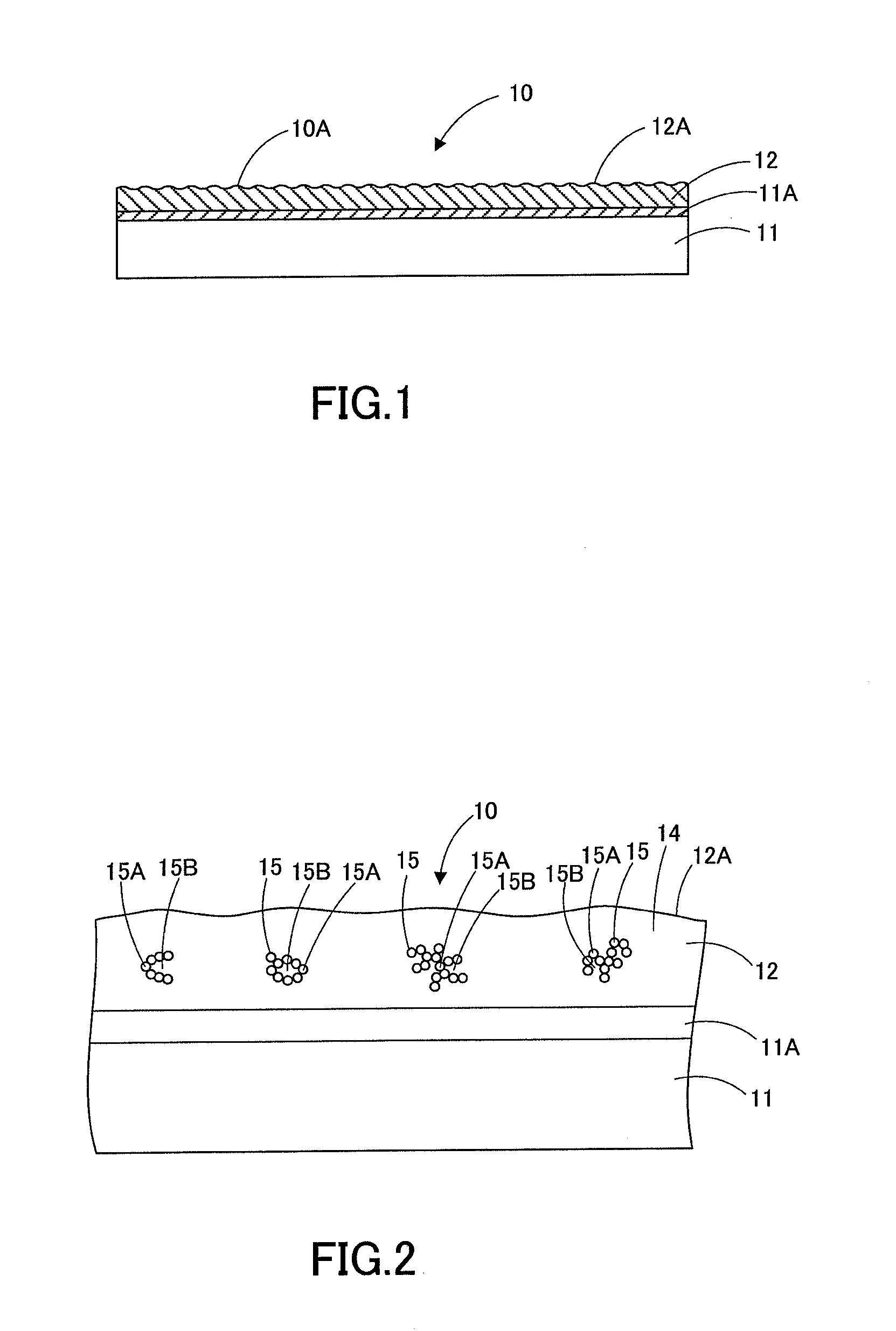
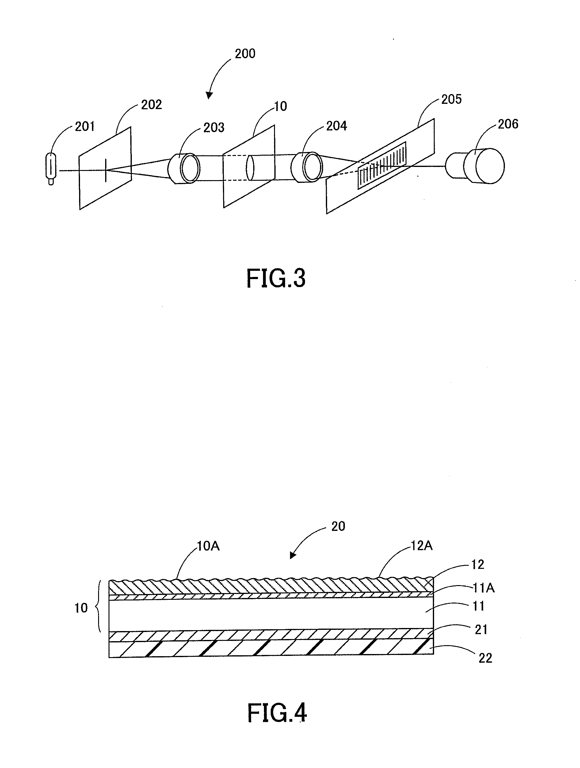
[0031]An antiglare film according to the first embodiment of the present invention will be described below with reference to the drawings. FIG. 1 is a schematic view illustrating the configuration of the antiglare film according to the present embodiment, FIG. 2 is a view of an enlarged part of FIG. 1, and FIG. 3 is a schematic view illustrating the state of measuring the transmission image sharpness of the antiglare film according to the present embodiment with a transmission image sharpness measurement apparatus. As used herein, the terms “film”, “sheet”, “plate”, and the like are based only on differences in names and not distinguished from each other. Thus, for example, “film” is a concept encompassing a member that can also be called a sheet or a plate. As one specific example, “antiglare film” also encompasses a member called “antiglare sheet”, “antiglare plate”, or the like.

Antiglare Film

[0032]As illustrated in FIG. 1, the antiglare film 10 includes a light transmissive subst...

second embodiment

[0151]An antiglare film according to a second embodiment of the present invention will be described below with reference to the drawings. In the second embodiment, a content overlapping with that in the first embodiment should be omitted unless otherwise specified. FIG. 7 is a schematic view illustrating the configuration of the antiglare film according to the present embodiment.

Antiglare Film

[0152]As illustrated in FIG. 7, an antiglare film 50 includes at least a light transmissive substrate 51, an antiglare layer 52 that is disposed on the light transmissive substrate 51 and includes a concavo-convex surface 52A, and a functional layer 53 disposed on the antiglare layer 52. The description of the light transmissive substrate 51 should be omitted in the present embodiment because the light transmissive substrate 51 is similar to the light transmissive substrate 11 described in the first embodiment. In the vicinity of the interface between the light transmissive substrate 51 and the...

third embodiment

[0181]An antiglare film according to a third embodiment of the present invention will be described below with reference to the drawings. In the third embodiment, a content overlapping with that in the first embodiment should be omitted unless otherwise specified. FIG. 8 is a schematic view illustrating the configuration of the antiglare film according to the present embodiment.

Antiglare Film

[0182]As illustrated in FIG. 8, an antiglare film 60 includes a light transmissive substrate 61 and an antiglare layer 62 that is disposed on the light transmissive substrate 61 and includes a concavo-convex surface 62A. In the antiglare film 60, in the vicinity of the interface between the light transmissive substrate 61 and the antiglare layer 62, it is preferable to form a mixture region 61A in which the light transmissive substrate 61 and a resin containing as a monomer unit a photopolymerizable monomer having a weight average molecular weight of 1000 or less are mixed as illustrated in FIG. ...


PUM

PropertyMeasurementUnit
hazeaaaaaaaaaa
hazeaaaaaaaaaa
wavelength cutoff wavelengthaaaaaaaaaa

Abstract

An antiglare film, including: a light transmissive substrate; and an antiglare layer that is disposed on a light transmissive substrate and includes a concavo-convex surface, wherein a surface of the antiglare film is a concavo-convex surface; the antiglare film has a total haze value of 0% or more and 5% or less; the antiglare film has an internal haze value of 0% or more and 5% or less; and assuming that a transmission image sharpness of the antiglare film, measured using an optical comb with a width of 0.125 mm, is C (0.125), and that a transmission image sharpness of the antiglare film, measured using an optical comb with a width of 0.25 mm, is C (0.25), an expression (1) and an expression (2) described below are satisfied:C(0.25)−C(0.125)≧2%  (1); andC(0.125)≧65%  (2).

Description

CROSS REFERENCE TO RELATED APPLICATION[0001]This application is a continuation of U.S. application Ser. No. 14 / 901,837, filed Dec. 29, 2015, which in turn is the National Stage of International Application No. PCT / JP2014 / 066251, filed Jun. 19, 2014, the entireties of which are incorporated herein by reference.FIELD OF THE INVENTION[0002]The present invention relates to antiglare films, polarizing plates, liquid crystal panels, and image display apparatuses.BACKGROUND OF THE INVENTION[0003]For suppressing reflections of an observer, the background of the observer, and the like, an antiglare film having concavities and convexities on a surface thereof or an antireflection film having an antireflection layer on an outermost surface thereof is generally disposed on an image display surface in an image display apparatus such as a liquid crystal display (LCD), a cathode ray tube display (CRT), a plasma display (PDP), an electroluminescence display (ELD), or a field emission display (FED)....

Claims


Application Information

Patent Timeline
Patent Type & Authority Applications(United States)
IPC IPC(8): G02B1/118G02B1/111G02F1/1335G02B5/30
CPCB32B7/02G02B5/305B32B2307/412B32B2307/42G02F1/133528G02B5/3033G02B1/111G02B1/118G02F1/133502G02B5/0294G02B5/02G02B1/11B32B7/023
Inventor EGUCHI, JUNYASOTODA, TEPPEIOGUMI, SHOICHIROMATSUYAMA, KOUSUKEFURUI, GEN
Owner DAI NIPPON PRINTING CO LTD
Why Eureka
Try Eureka