Shield member and protective cap

Inactive Publication Date: 2015-08-13
MIDORI ANZEN
View PDF11 Cites 2 Cited by
  • Summary
  • Abstract
  • Description
  • Claims
  • Application Information

AI Technical Summary

Benefits of technology

[0018]According to the present invention, in a shield member for covering a face of a wearer and a protective cap in which the shield member is provided, an effect in which image distortion is made as small as possible even when he or she sees an object through its peripheral portions of the shield member is provided.

Problems solved by technology

Thus the thickness of the shield plate is constant regardless of places, and it gives rise to a problem that, when a wearer see an object through the shield plate, he or she will not see a distorted image through its central portion but will see distorted images through its peripheries.

Method used


Image

  • Shield member and protective cap
  • Shield member and protective cap
  • Shield member and protective cap

Examples


first embodiment

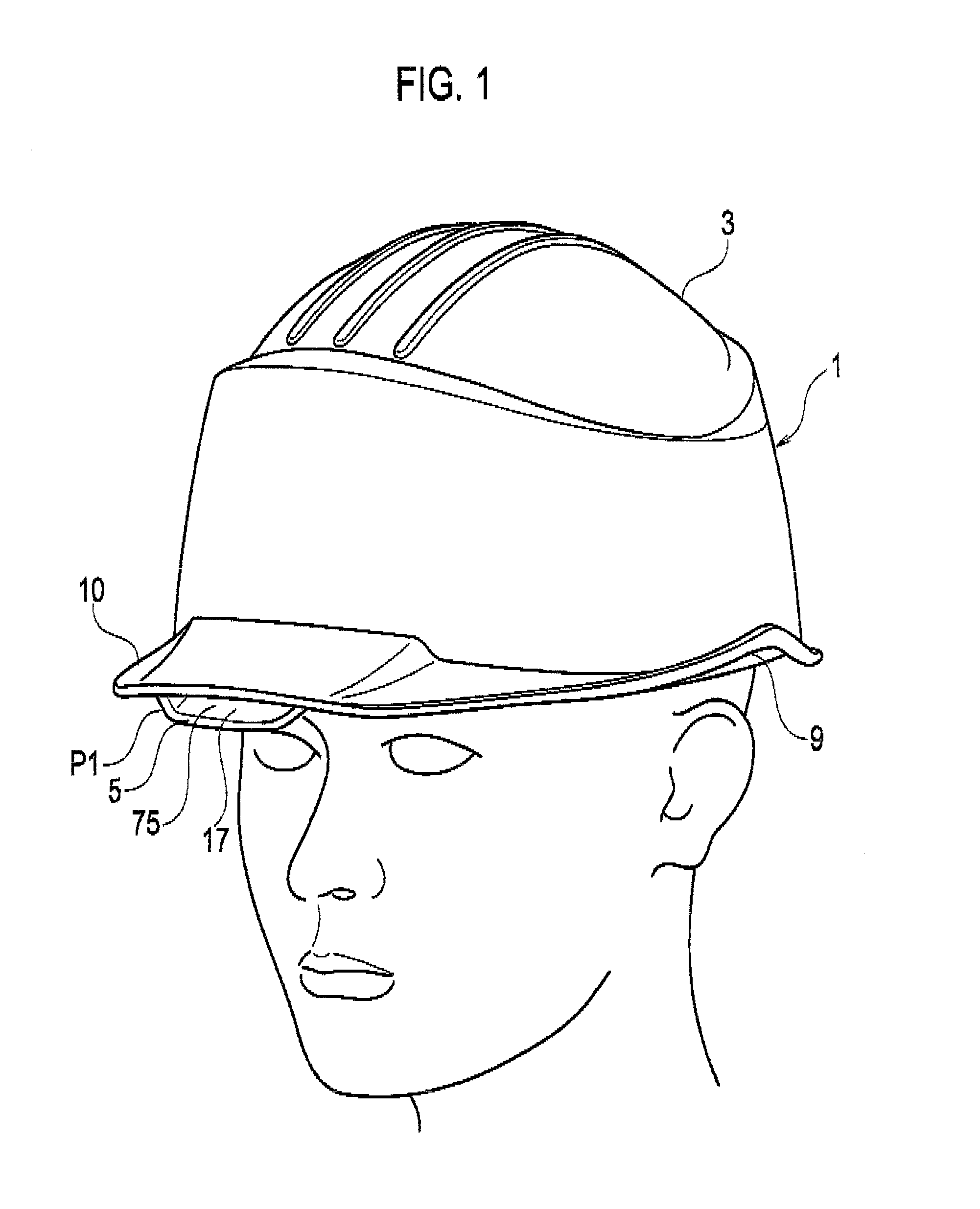
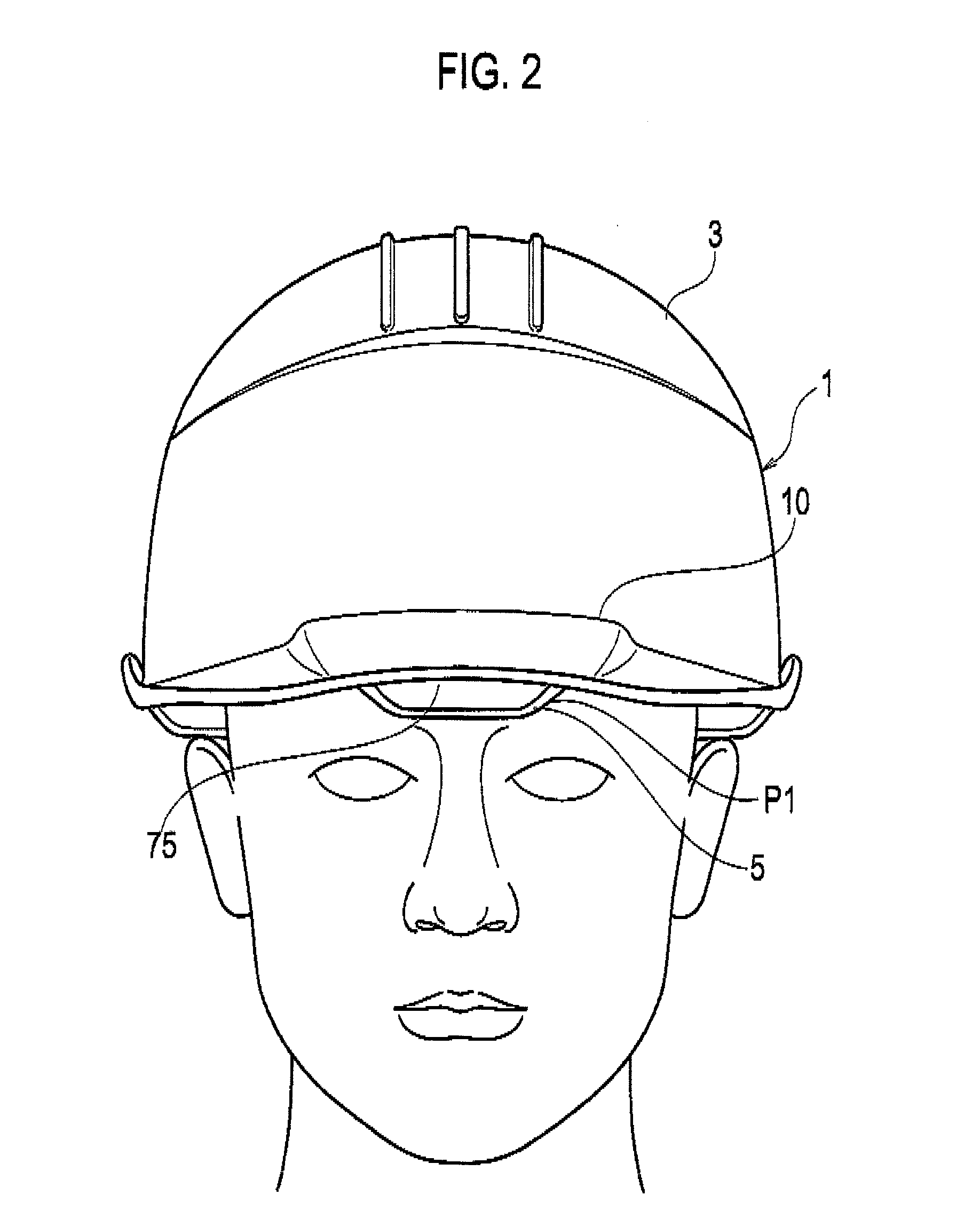
[0072]FIG. 1 and FIG. 4 are perspective views when a wearer wears a protective cap 1 in accordance with a first embodiment of the present invention, FIG. 2 and FIG. 5 are elevational views when the wearer wears the protective cap 1, and FIG. 3 and FIG. 6 are side views when the wearer wears the protective cap 1.

[0073]Meanwhile, FIG. 1, FIG. 2 and FIG. 3 show a state where the shield plate 5 is positioned at a housing position P1, and FIG. 4, FIG. 5 and FIG. 6 show a state where the shield plate 5 is positioned at a shielding position P3.

[0074]FIG. 7 is a cross sectional view of the protective cap 1 taken from a plane extending in a front-and-rear and upper-and-rear directions relative to the protective cap 1 through a center of the protective cap 1.

[0075]FIG. 9 and FIG. 10 are perspective views showing a state where the guide member 11 and the shield plate 5 are assembled. Meanwhile, FIG. 9 shows a state where the shield plate 5 is positioned at the housing position P1, and FIG. 10 ...

second embodiment

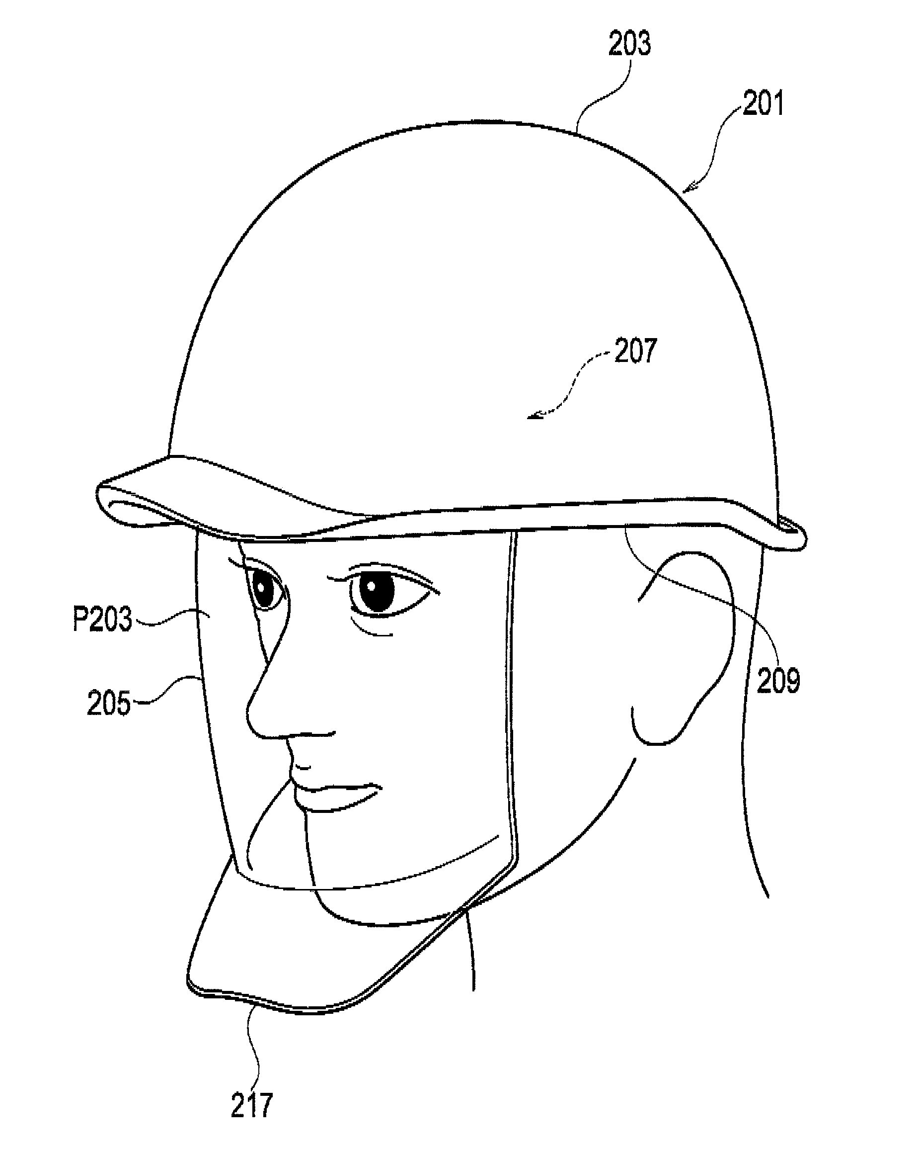
[0147]FIG. 21 and FIG. 22 are perspective views when a wearer wears a protective cap 201 in accordance with the second embodiment of the present invention, FIG. 23 is a cross sectional view of the protective cap 201, and FIG. 24 and FIG. 25 are views of the protective cap 201 viewed from its inside.

[0148]Meanwhile FIG. 21 and FIG. 24 show a state where the shield plate 205 is positioned at a housing position P201, and FIG. 22 and FIG. 25 show a state where the shield plate 205 is positioned at a shielding position P203. Further, FIG. 23 is a cross sectional view taken from a plane extending in the upper-and-lower direction of the protective cap 201 through a center of the protective cap 201.

[0149]The protective cap (helmet with a shield face) 201 is constituted to for example comprise a cap body 203 formed to be substantially bilaterally symmetrical, a shield plate 205, and a guide means 207 for guiding the shield plate 205.

[0150]The cap body 203 is to protect a head of a wearer, an...

third embodiment

[0197]FIG. 28 is a drawing showing a summarized configuration of a protective cap 301 in accordance with a third embodiment of the present invention, FIG. 29 is drawing showing differences in outlines of a cap body 303 of the protective cap 301 and a cap body 300 of a widely-used protective cap, and FIG. 30 is a cross sectional view of the protective cap 301 (a cross sectional view taken from a plane extending in the front-and-rear and upper-and-lower directions of the protective cap 301 through a center of the protective cap 301).

[0198]FIG. 31 is a drawing showing a state where a wearer wears the protective cap 301. (a) and (b) of FIG. 31 show a state where a shield plate 305 is positioned at a housing position P301, and (c) and (d) of FIG. 31 show a state where the shield plate 305 is positioned at shielding position P303.

[0199]The protective 301 is constituted to comprise a cap body 303 and a shield plate (shield member; face body) 305. The cap body 303 and the shield plate 305 a...


PUM


Abstract

In a shield member for covering a face of a wearer and a protective cap in which the shield member is provided, image distortion is made as small as possible even when he or she sees an object through its peripheral portions of the shield member. In a shield member 5 for covering a face of a wearer installed in a cap body 3 for protecting a hear of the wearer, it is a shield member 5 formed of a transparent body or a translucent body in a curved plate-like form and gradually becoming thinner as going from its central portion to its peripheral portion.

Description

TECHNICAL FIELD[0001]The present invention relates to a shield member and a protective cap, and in particular relates to that configured to cover a face of a wearer.BACKGROUND ART[0002]There is so far known a protective cap (helmet) with a shield (transparent or translucent shield plate) for protecting eyes of a worker as a measure against accidents in which nails bounce back out of nailers to stick in worker's eyes or any others occur during works of construction of a house (see PTL1-PTL3, for example).CITATION LISTPatent Literature[0003]PTL 1: Japanese Unexamined Patent Publication No. 2003-049316[0004]PTL 2: Japanese Unexamined Patent Publication No. 2003-253519[0005]PTL Japanese Unexamined Patent publication No. 2003-082518SUMMARY OF INVENTIONProblem to be Solved[0006]However, in regard to a shield plates provided in any of the aforementioned conventional protective caps, a base material formed of a transparent material such as a resin in a plate-like shape is heated, deformed a...

Claims


Application Information

Patent Timeline
Patent Type & Authority Applications(United States)
IPC IPC(8): A42B3/22
CPCA42B3/225A42B3/042A42B3/08A42B3/227
Inventor OKUMA, WATARUNAKAYAMA, FUMIHARUTAJIMA, NORITAKA
Owner MIDORI ANZEN
Why Eureka
Try Eureka