Charged particle beam analysis while part of a sample to be analyzed remains in a generated opening of the sample

a particle beam and charge technology, applied in the field of sample analysis, can solve the problems of sample contamination sample to be analyzed, etc., and achieve the effect of preventing further examination with the aid of the second particle beam device (transmission electron microscope)

Active Publication Date: 2013-08-06
CARL ZEISS MICROSCOPY GMBH
View PDF29 Cites 0 Cited by
  • Summary
  • Abstract
  • Description
  • Claims
  • Application Information

AI Technical Summary

Benefits of technology

[0011]In the method according to the system described herein, a part of the sample to be analyzed and removed from the sample may be analyzed by detecting the particles backscattered from the part of the sample to be analyzed or emitted from the part of the sample to be analyzed. Particles emitted from the part of the sample to be analyzed are understood as particles whose kinetic energy at least substantially differs from the kinetic energy of the particles in the particle beam incident on the part of the sample to be analyzed, in particular particles that have a kinetic energy of less than 100 eV. According to the method, it is possible, for analyzing the part of the sample to be analyzed, to detect only particles that exit on the side of the part of the sample to be analyzed which is hit by the particle beam. In this way the part of the sample to be analyzed may have a substantially greater thickness than in methods in which particles transmitted through the sample are detected. This makes generating the part of the sample to be analyzed having the relevant cross-section of the sample less critical and simpler.
[0013]The system described herein therefore has the advantage that the part of the sample to be analyzed, after being separated from the sample material, does not have to be taken out of the particle beam device for further examination. Thus, contamination of the part of the sample to be analyzed prior to being examined is prevented. In contrast with the prior art in which the part of the sample is taken out, as discussed above, the method according to the system described herein is also less time-consuming. In addition, the risk of damaging the part of the sample to be analyzed, which may well happen in a taking-out operation, is reduced. Furthermore, it is advantageous in the method according to the system described herein that particles backscattered and / or emitted from the part of the sample to be analyzed may be detected and used for the analysis. In particular, backscattered electrons and / or emitted electrons (secondary electrons) are detected. In addition, the part of the sample to be analyzed may be irradiated using a particle beam for examining the part to be analyzed in such a way that the particle beam may be directed perpendicularly or at least approximately perpendicularly onto the part of the sample to be analyzed. The part of the sample to be analyzed does not have to be tilted and is not situated at an oblique angle to the incident particle beam. In this way, high spatial resolution is achieved. Furthermore, image distortions, which have been described above, are prevented.
[0022]In another embodiment of the method according to the system described herein, at least one section surface, which is initially positioned perpendicularly or at least approximately perpendicularly to a surface of the sample, may be generated by separating the part of the sample to be analyzed from the sample material. The section surface may be placed in the opening when positioning the part of the sample to be analyzed in such a way that the section surface is parallel or at least approximately parallel to the surface of the sample. In this way it is then possible to easily examine the section surface with the aid of the particle beam. In particular it is possible to examine the section surface by irradiating it perpendicularly with the aid of the particle beam. When using a first particle beam and a second particle beam, the section surface may be examined with the aid of the second particle beam for example. In another embodiment, it is provided that, prior to placing the part of the sample to be analyzed in the opening, the section surface may be prepared, in particular, polished, with the aid of the particle beam. The section surface may be oriented approximately parallel to the incident particle beam during the preparation. When using a first particle beam and a second particle beam, the first particle beam may be used for the preparation, for example.
[0026]In yet another embodiment of the method according to the system described herein, multiple openings are provided. Thus, the opening already described previously may be configured as a first opening, which may be adjacent to a first side of the part of the sample to be analyzed. In addition, when the part of the sample to be analyzed is separated from the sample material, a second opening may also be generated, the second opening being situated on a second side of the part of the sample to be analyzed which lies opposite to the first side of the part of the sample to be analyzed. It is also provided that, after placing the part of the sample to be analyzed in the opening, the second side of the part of the sample to be analyzed may face the incident particle beam, for example, the second particle beam. Thus, the second side, which will be examined in greater detail with the aid of the particle beam, for example, the second particle beam, may be basically exposed relatively late. The risk of the second side being contaminated is thus reduced. The second side may correspond to the above-mentioned section surface.
[0032]Commercially available scanning electron microscopes make electron probes possible whose diameters are so small that the achievable resolutions perpendicularly to the direction of incidence of an electron beam are less than 5 nm, sometimes even less than 1 nm, in particular when the surface of the sample to be analyzed is oriented perpendicularly to the optical axis of the device and may be positioned at a sufficiently small working distance of a few (1 to 5) mm from the objective of the scanning electron microscope. The above-described methods according to the system described herein may therefore be carried out without difficulties using regular scanning electron microscopes.

Problems solved by technology

It is, however, disadvantageous in this known method that the part of the sample to be analyzed must be taken out of the first particle beam device and taken into the second particle beam device.
It may well happen then that the part of the sample to be analyzed is contaminated in such a way that further examination with the aid of the second particle beam device (transmission electron microscope) can no longer be performed.
In addition, the method is very time-consuming due to the taking-out operation.
Furthermore, taking out always carries the risk that the part of the sample to be analyzed becomes damaged, so that it may not be further examined.
However, only an examination that does not provide sufficient spatial resolution is then possible.
This impairs the spatial resolution.
In addition, an image of the part of the sample to be analyzed may be distorted.
Therefore, generating the sample or the part of the sample to be analyzed is very complicated because the sample must be generated in the form of a thin sample slice having a thickness of only a few nm, which, however, must still contain the relevant part of the sample.

Method used


Image

  • Charged particle beam analysis while part of a sample to be analyzed remains in a generated opening of the sample
  • Charged particle beam analysis while part of a sample to be analyzed remains in a generated opening of the sample
  • Charged particle beam analysis while part of a sample to be analyzed remains in a generated opening of the sample

Examples


Embodiment Construction

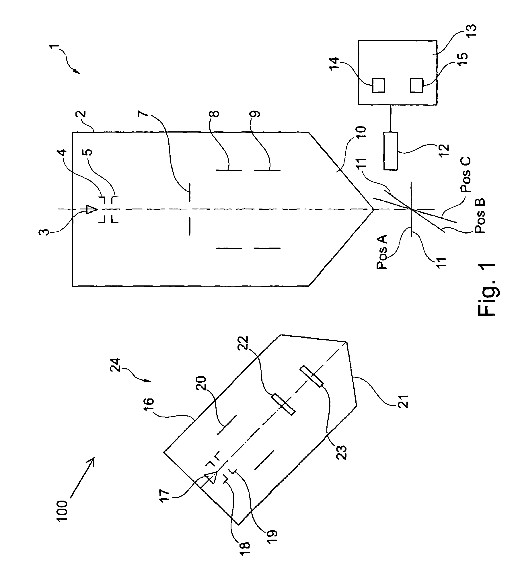
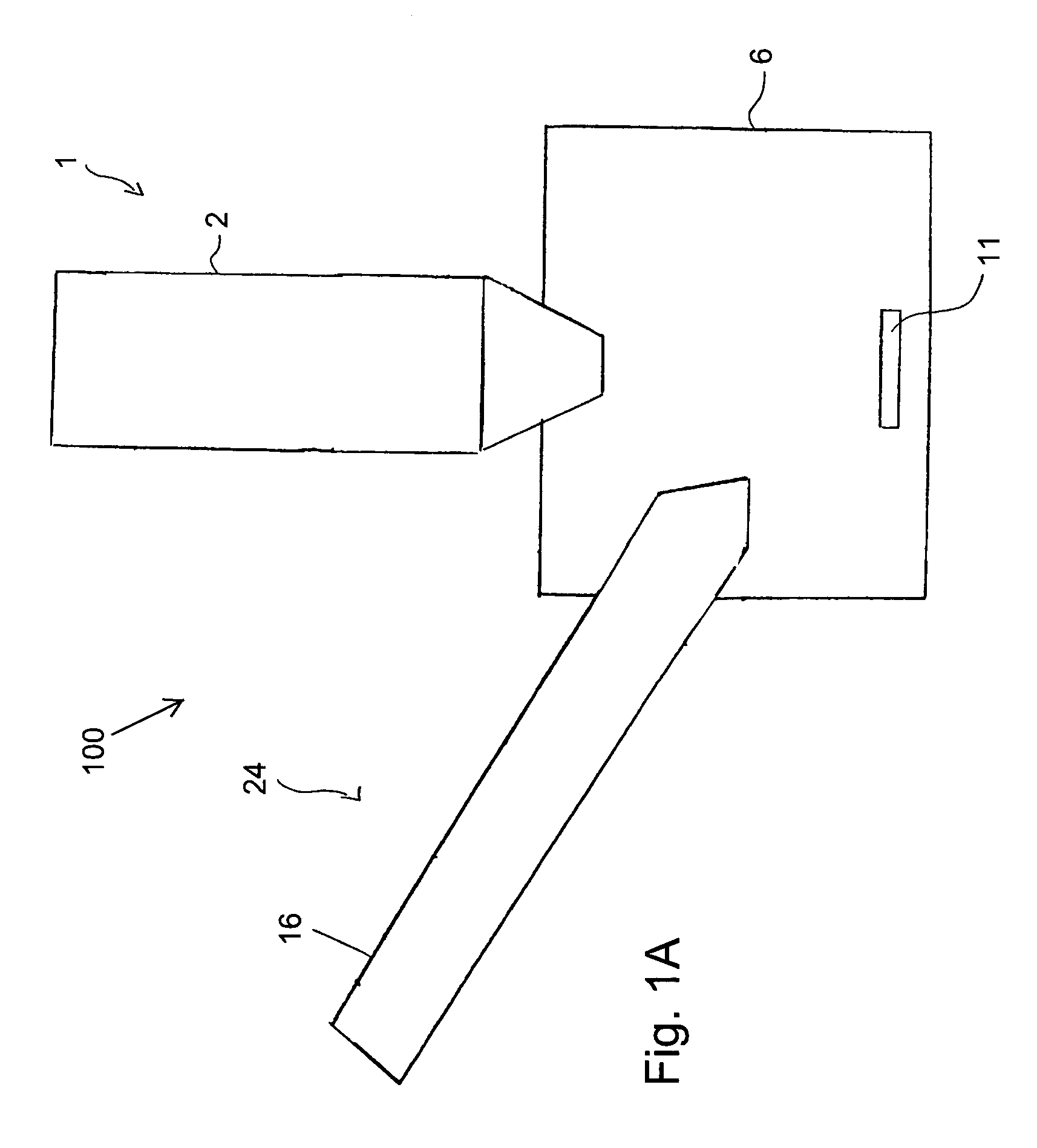
[0044]FIGS. 1 and 1A show a schematic representation of a particle beam device 100 which has an ion beam device 1 and an electron beam device 24, which are arranged at a sample chamber 6 (vacuum chamber) according to an embodiment of the system described herein. Methods for analyzing a sample, as further discussed elsewhere herein, may be carried out using the illustrated particle beam device 100.

[0045]The ion beam device 1 may have an ion beam column 2 in which numerous units of the ion beam device 1 are situated. In particular, an ion source 3 may be situated in the ion beam column 2. The ion source 3 may generate ions which form an ion beam in the ion beam column 2. The ions may be accelerated to a predefinable potential with the aid of an electrode 4 and then passed through a condenser lens 5. The ion beam formed by the ions may be passed through an aperture 7 and then reach a first deflecting system 8 and a second deflecting system 9, which may comprise a scanning device. The i...


PUM


Abstract

A device and method for analyzing a sample provide for extracting a part to be analyzed from the sample with the aid of a previously generated opening in the sample. The part to be analyzed is examined in greater detail with the aid of a particle beam. For this purpose, the sample is placed in the opening or on a sample holder.

Description

TECHNICAL FIELD[0001]This application relates to a device and method for analyzing a sample and, in particular, analyzing a sample using a particle beam device.BACKGROUND OF THE INVENTION[0002]In the field of material analysis, for example, in the field of semiconductor technology, cross sections of a sample are generated and examined in detail.[0003]For this purpose, a method is known from the prior art in which a sample is initially prepared and subsequently examined in a particle beam device. The sample is prepared in a first particle beam device, which has both an electron beam column and an ion beam column. With the aid of an electron beam, which is provided by the electron beam column, a part of the sample to be analyzed is initially identified. This part of the sample to be analyzed is then prepared with the aid of an ion beam which is provided by the ion beam column and cut out of the sample. The part of the sample that has been cut out and is to be analyzed is subsequently ...

Claims


Application Information

Patent Timeline
Patent Type & Authority Patents(United States)
IPC IPC(8): G21K5/10G01F23/00
CPCG01N1/286H01J2237/31745
Inventor ZEILE, ULRIKEDONITZ, DIETMAR
Owner CARL ZEISS MICROSCOPY GMBH
Why Eureka
Try Eureka