[0011]In the method according to the
system described herein, a part of the sample to be analyzed and removed from the sample may be analyzed by detecting the particles backscattered from the part of the sample to be analyzed or emitted from the part of the sample to be analyzed. Particles emitted from the part of the sample to be analyzed are understood as particles whose
kinetic energy at least substantially differs from the
kinetic energy of the particles in the particle beam incident on the part of the sample to be analyzed, in particular particles that have a
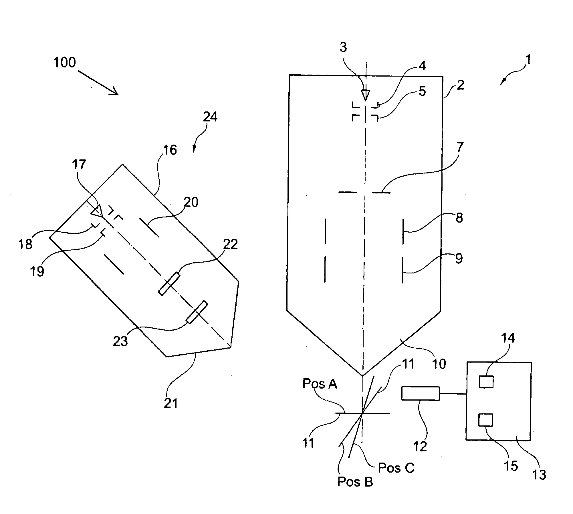
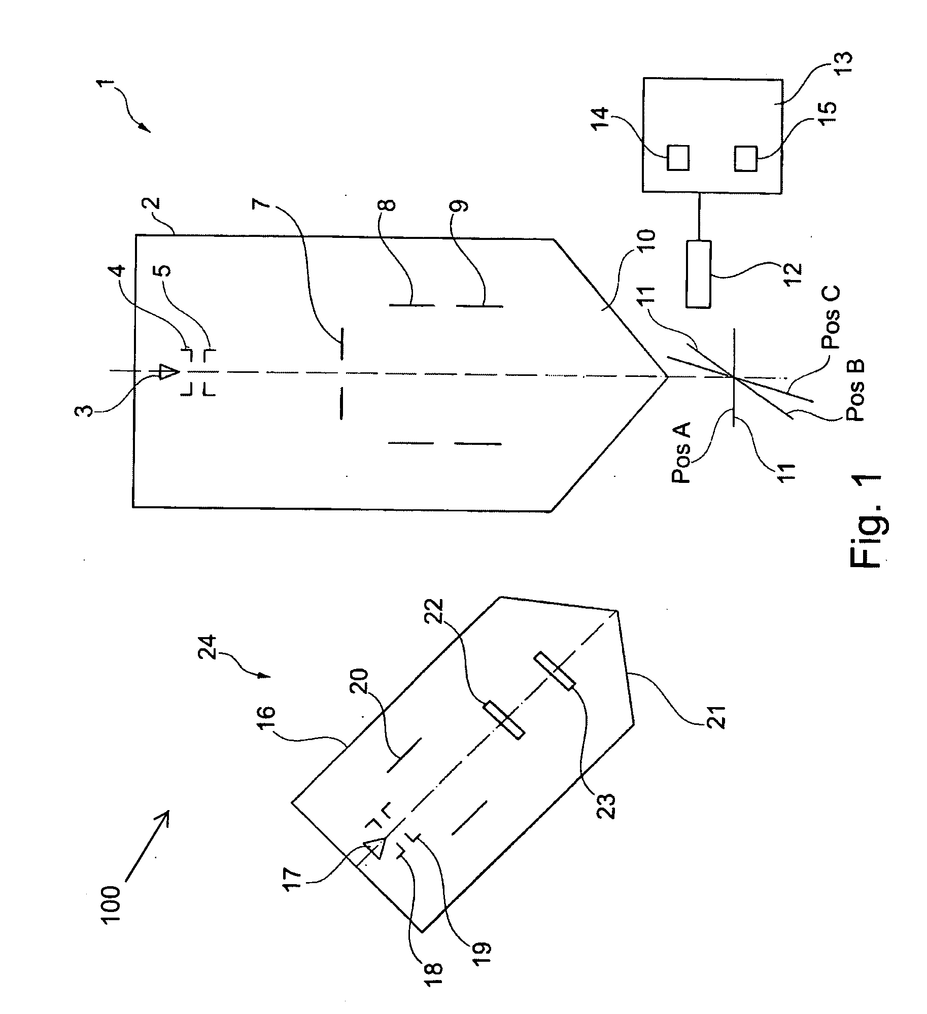
kinetic energy of less than 100 eV. According to the method, it is possible, for analyzing the part of the sample to be analyzed, to detect only particles that exit on the side of the part of the sample to be analyzed which is hit by the particle beam. In this way the part of the sample to be analyzed may have a substantially greater thickness than in methods in which particles transmitted through the sample are detected. This makes generating the part of the sample to be analyzed having the relevant cross-section of the sample less critical and simpler.
[0013]The
system described herein therefore has the
advantage that the part of the sample to be analyzed, after being separated from the sample material, does not have to be taken out of the particle beam device for further examination. Thus,
contamination of the part of the sample to be analyzed prior to being examined is prevented. In contrast with the prior art in which the part of the sample is taken out, as discussed above, the method according to the
system described herein is also less time-consuming. In addition, the risk of damaging the part of the sample to be analyzed, which may well happen in a taking-out operation, is reduced. Furthermore, it is advantageous in the method according to the system described herein that particles backscattered and / or emitted from the part of the sample to be analyzed may be detected and used for the analysis. In particular, backscattered electrons and / or emitted electrons (
secondary electrons) are detected. In addition, the part of the sample to be analyzed may be irradiated using a particle beam for examining the part to be analyzed in such a way that the particle beam may be directed perpendicularly or at least approximately perpendicularly onto the part of the sample to be analyzed. The part of the sample to be analyzed does not have to be tilted and is not situated at an
oblique angle to the incident particle beam. In this way,
high spatial resolution is achieved. Furthermore, image distortions, which have been described above, are prevented.
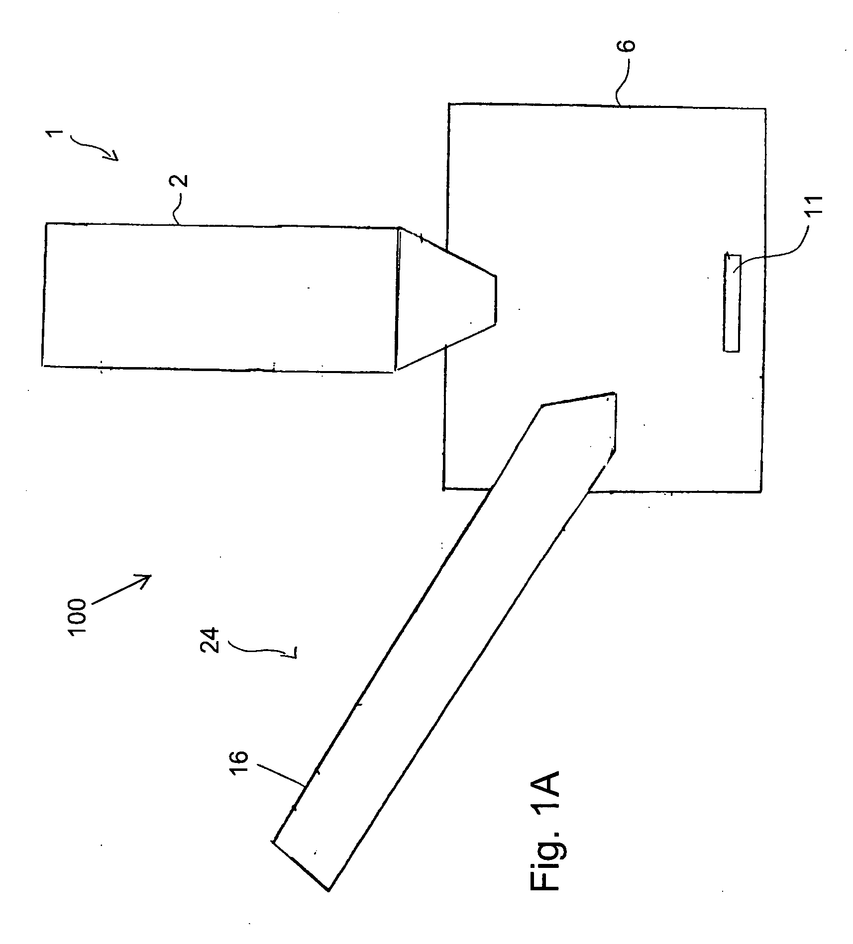
[0022]In another embodiment of the method according to the system described herein, at least one section surface, which is initially positioned perpendicularly or at least approximately perpendicularly to a surface of the sample, may be generated by separating the part of the sample to be analyzed from the sample material. The section surface may be placed in the opening when positioning the part of the sample to be analyzed in such a way that the section surface is parallel or at least approximately parallel to the surface of the sample. In this way it is then possible to easily examine the section surface with the aid of the particle beam. In particular it is possible to examine the section surface by irradiating it perpendicularly with the aid of the particle beam. When using a first particle beam and a second particle beam, the section surface may be examined with the aid of the second particle beam for example. In another embodiment, it is provided that, prior to placing the part of the sample to be analyzed in the opening, the section surface may be prepared, in particular, polished, with the aid of the particle beam. The section surface may be oriented approximately parallel to the incident particle beam during the preparation. When using a first particle beam and a second particle beam, the first particle beam may be used for the preparation, for example.
[0026]In yet another embodiment of the method according to the system described herein, multiple openings are provided. Thus, the opening already described previously may be configured as a first opening, which may be adjacent to a first side of the part of the sample to be analyzed. In addition, when the part of the sample to be analyzed is separated from the sample material, a second opening may also be generated, the second opening being situated on a second side of the part of the sample to be analyzed which lies opposite to the first side of the part of the sample to be analyzed. It is also provided that, after placing the part of the sample to be analyzed in the opening, the second side of the part of the sample to be analyzed may face the incident particle beam, for example, the second particle beam. Thus, the second side, which will be examined in greater detail with the aid of the particle beam, for example, the second particle beam, may be basically exposed relatively late. The risk of the second side being contaminated is thus reduced. The second side may correspond to the above-mentioned section surface.
[0032]Commercially available scanning electron microscopes make electron probes possible whose diameters are so small that the achievable resolutions perpendicularly to the direction of incidence of an electron beam are less than 5 nm, sometimes even less than 1 nm, in particular when the surface of the sample to be analyzed is oriented perpendicularly to the
optical axis of the device and may be positioned at a sufficiently small working distance of a few (1 to 5) mm from the objective of the
scanning electron microscope. The above-described methods according to the system described herein may therefore be carried out without difficulties using regular scanning electron microscopes.

