

Liquid discharge device and media reel-out method
a technology of liquid discharge device and media reel, which is applied in the direction of thin material processing, printing, other printing apparatuses, etc., can solve the problems of increasing assembly cost and production cost, and achieve the effect of reducing the number of sensors and suppressing the meandering of media
- Summary
- Abstract
- Description
- Claims
- Application Information
AI Technical Summary
Benefits of technology
Problems solved by technology
Method used
Image

Examples
embodiment 1
FIG. 1 through FIG. 3C
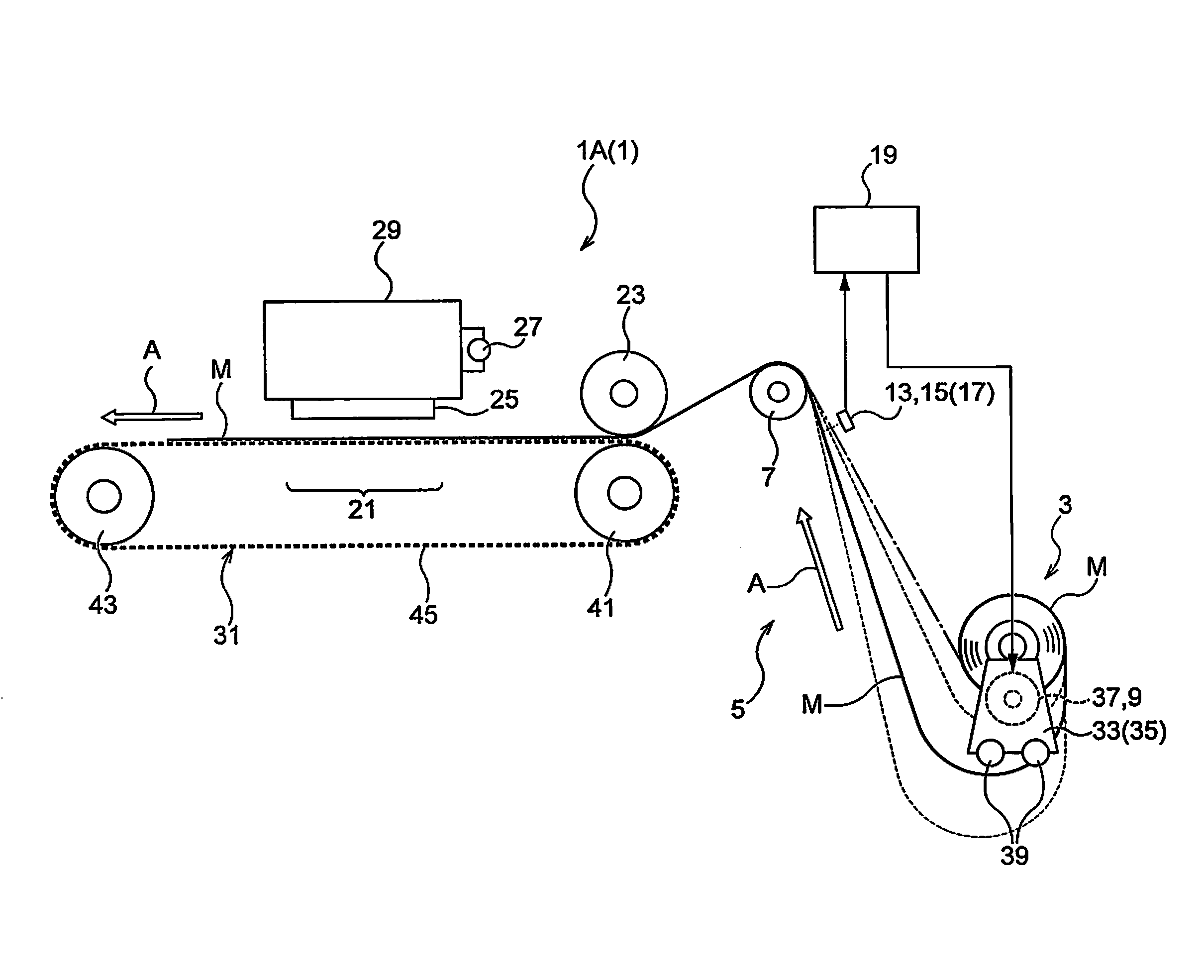
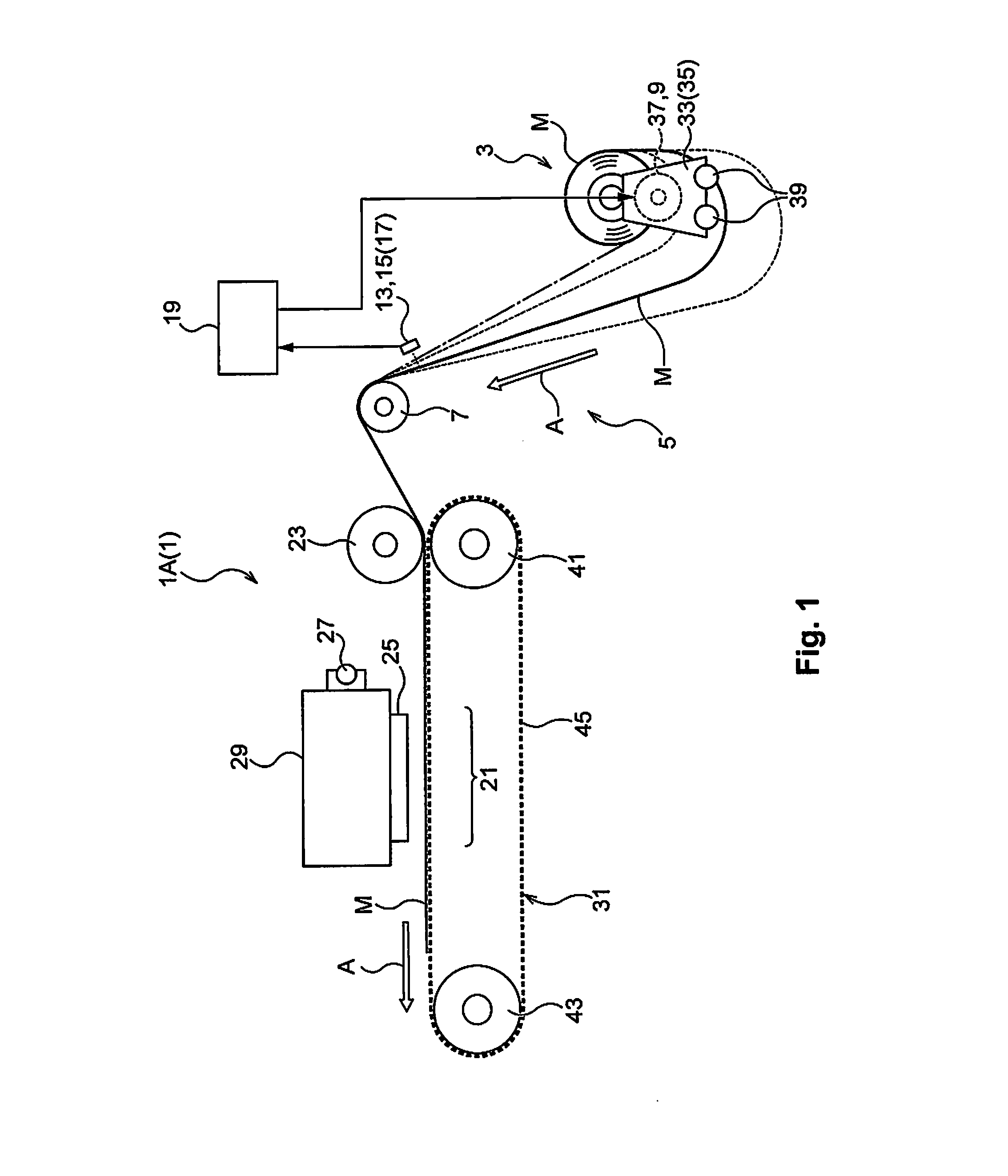
[0058]The liquid discharge device 1A(1) of this embodiment is an inkjet printing device that uses fabric rolled into roll form as media M. Here, “fabric” is a textile product of natural fibers such as cotton, hemp, silk or the like, chemical fibers such as nylon, polyester or the like, or a fabric or textile using as a source thread an item for which these are mixed or the like.
(1) Schematic Constitution of the Liquid Charge Device (see FIG. 1 through FIG. 3C)
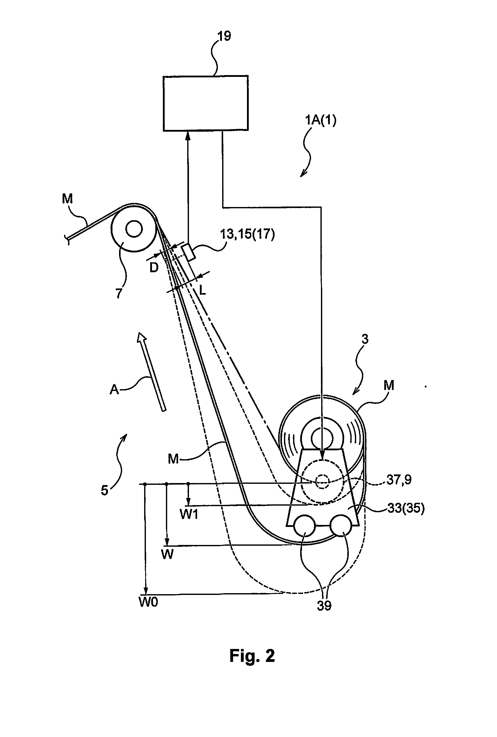
[0059]The liquid discharge device 1A of this embodiment is basically constituted by being equipped with a media reel-out unit 3 that reels out media M rolled into roll form, and a reel-out volume adjustment unit 9 that adjusts the reel-out volume of the media M reeled out from the media reel-out unit 3 based on changes in a slack volume W of the media M with a media slack state part 5 produced at a position downstream from the media reel-out unit 3.
[0060]There are provided a first sensor 13 (see FIG. 3C) a...
embodiment 2
FIGS. 4A to 4C
[0085]The liquid discharge device 1B(1) of embodiment 2 is the same as the liquid discharge device IA of embodiment 1 for the constitution other than the only difference which is the arrangement of the first sensor 13 and the second sensor 15, and the control contents with the control unit 19 accompanying this.
[0086]Therefore, here, a description of the same constitution as that of embodiment 1 will be omitted, and the description will be focused on the constitutions unique to embodiment 2.
[0087]Specifically, with this embodiment 2, the arrangement of the sensor pair 17 for which only one set is provided is different from embodiment 1, whereby the first sensor 13 is arranged at a position facing one edge part 11A in the width direction B of the slack state media M, and the second sensor 15 is arranged at a position facing the other edge part 11B in the width direction B of the slack state media M.
[0088]Specifically, during normal times when the media M reel-out is perf...
embodiment 3
FIGS. 5A and 5B
[0096]The liquid discharge device 1C(1) of embodiment 3 is the same as the liquid discharge device 1A of embodiment 1 described previously for the constitution other than the only difference which is the arrangement of the second sensor 15.
[0097]Therefore, here, a description of the same constitution as that of embodiment 1 will be omitted, and the description will be focused on the constitutions unique to embodiment 3.
[0098]Specifically, with this embodiment 3, the arrangement of the sensor pair 17 for which only one set is provided is different from embodiment 1, whereby the first sensor 13 and the second sensor 15 are arranged at positions skewed in the reel-out direction A of the media M.
[0099]In specific terms, as shown in FIGS. 5A and 5B, an arrangement of the sensor pair 17 is used for which the second sensor 15 is positioned further to the upstream side toward the media reel-out unit 3 side than the position of the first sensor 13.
[0100]Then, with this liquid ...
PUM
 Abstract
Description
Claims
Application Information