Tread for pneumatic tire

a pneumatic tire and tread technology, applied in the field of pneumatic tire treads, can solve the problems of reducing handling stability on a wet road surface, reducing the water drainage properties between the pneumatic tire and the road surface, etc., and achieves the effects of reducing air column resonance, and maintaining water drainage properties

Active Publication Date: 2015-09-03
MICHELIN & CO CIE GEN DES ESTAB MICHELIN
View PDF8 Cites 3 Cited by
  • Summary
  • Abstract
  • Description
  • Claims
  • Application Information

AI Technical Summary

Benefits of technology

[0045]According to an embodiment of the invention configured in the manner described above, it is possible to maintain water drainage properties while reducing air column resonance, and the water drainage properties can be maintained up to the final stage of wear. That is to say, if the thickness of the flexible fences is less than 0.3 mm, the flexible fences collapse under air pressure due to a reduction in dimensional strength thereof and there is a risk of a reduction in the effect of reducing air column resonance. On the other hand, if the thickness of the flexible fences is greater than 2.0 mm, the proportion of cross-sectional opening in the main groove when the flexible fences collapse inside the main groove is reduced so there is a risk of deterioration of the water drainage properties.
[0046]By virtue of the pneumatic tire tread according to an embodiment of the invention it is possible to maintain the water drainage performance up to the final stage of wear of the tread part while reducing air column resonance and maintaining water drainage performance.

Problems solved by technology

However, by providing this kind of member to obstruct the flow of air in the direction in which the main groove is formed, the flow of water penetrating into the main groove is also obstructed inside the main groove when the vehicle is travelling over a wet road surface and there is a reduction in the water drainage properties between the pneumatic tire and the road surface, so handling stability on a wet road surface is reduced.

Method used


Image

  • Tread for pneumatic tire
  • Tread for pneumatic tire
  • Tread for pneumatic tire

Examples


Embodiment Construction

[0057]Preferred modes of embodiment of the invention will be described below with reference to the figures.

[0058]The pneumatic tire tread according to a first mode of embodiment of the invention will be described first of all with the aid of FIG. 1 to 3.

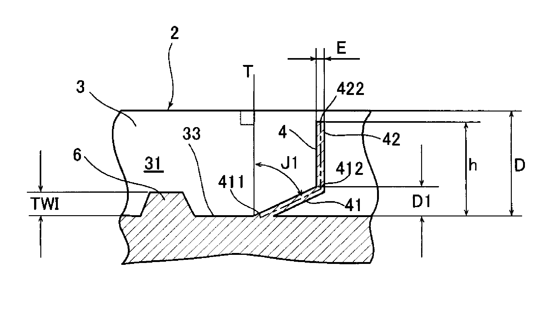
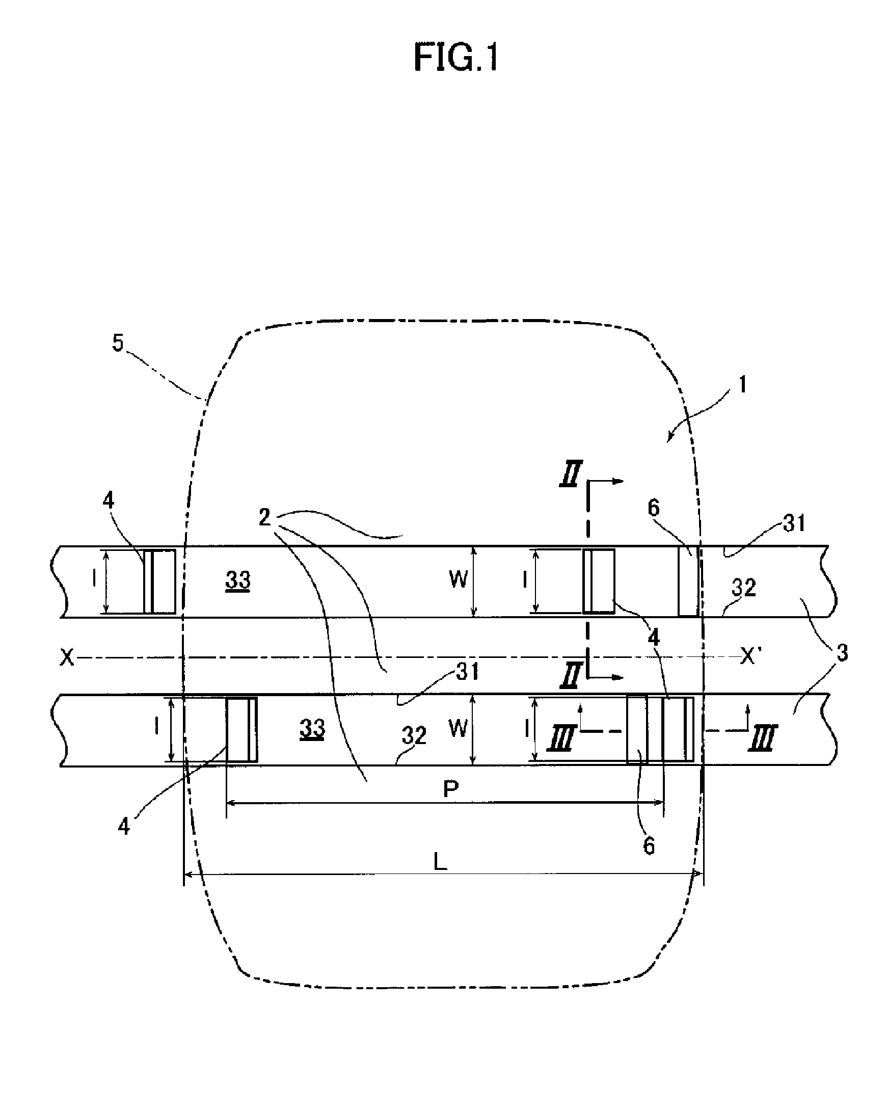
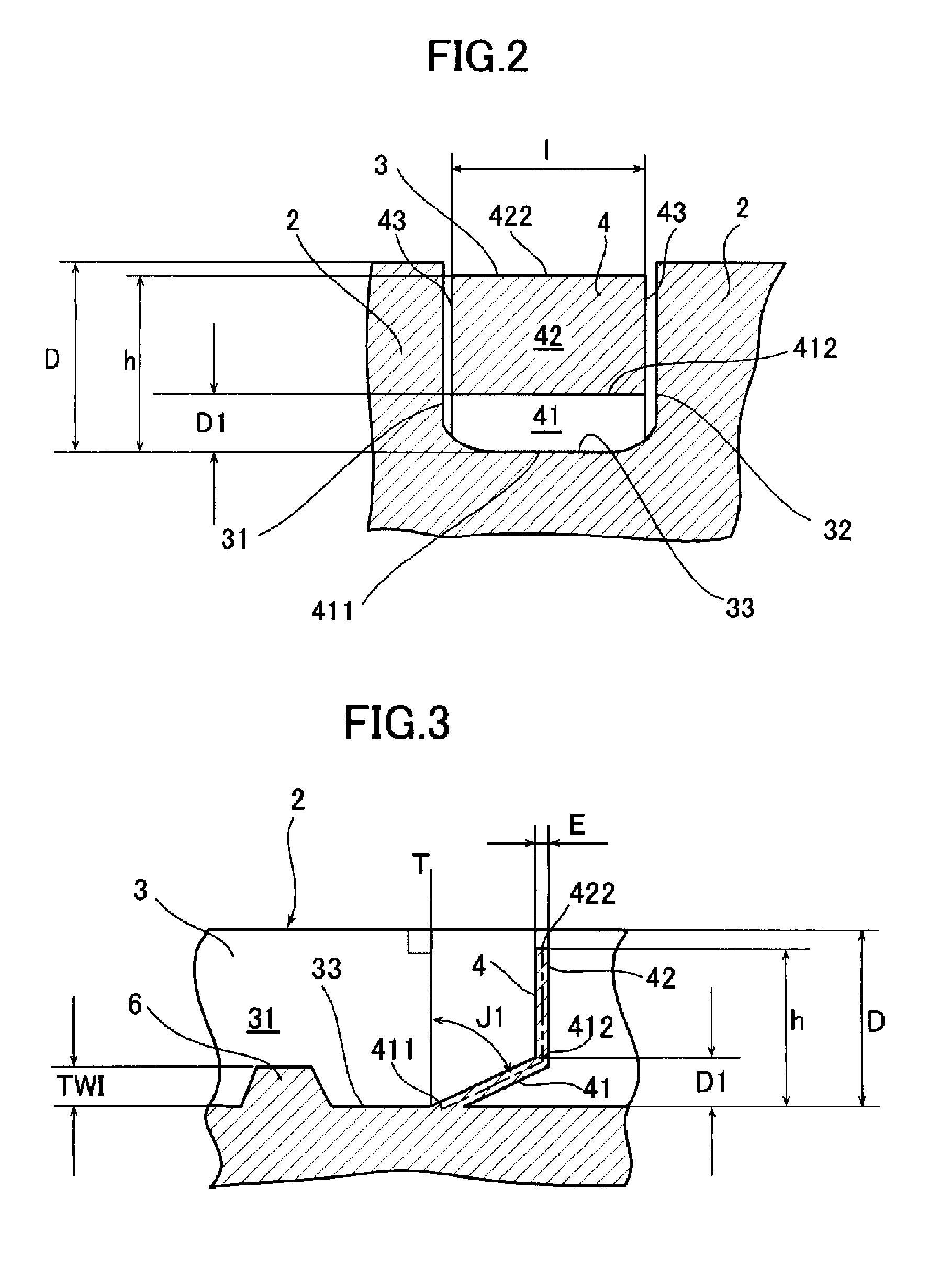
[0059]FIG. 1 schematically shows the pneumatic tire tread according to the first mode of embodiment of the invention, FIG. 2 is an enlargement in cross section of the pneumatic tire tread seen along the line II-II in FIG. 1, and FIG. 3 is an enlargement in cross section of the pneumatic tire tread seen along the line III-III in FIG. 1.

[0060]First of all, as shown in FIG. 1, the reference symbol 1 denotes a pneumatic tire according to this mode of embodiment, the pneumatic tire 1 comprising a tread part 2, and two main grooves 3 having a width W and extending in the tire circumferential direction indicated by XX′ are formed in the tread part 2. The main groove 3 has three surfaces, namely opposing wall surfaces 31, 32 and a bottom sur...


PUM


Abstract

A pneumatic tire tread that maintains a good level of water drainage performance up to the final stage of wear of a tread part formed with a plurality of flexible fences which are disposed inside at least one main groove extending from the bottom surface of the main groove and obstructing at least 70% of the cross-sectional area of the main groove, the flexible fences comprising an inside portion having a connecting part which is connected to the main groove, and an outside portion which is radially outside a predetermined height D1 from the bottom surface of the main groove, and the average angle of inclination of the inside portion with respect to a line perpendicular to the surface of the tread part in contact with the road surface is greater than the average angle of inclination of the outside portion.

Description

[0001]This application claims benefit of the filing date of PCT / JP2012 / 058340, filed 29 Mar. 2012, the entire contents of which is incorporated herein by reference for all purposes.BACKGROUND[0002]1. Technical Field[0003]The present disclosure relates to a pneumatic tire tread, and more specifically the present disclosure relates to a pneumatic tire tread with which air column resonance can be reduced by the formation of flexible fences in a tread main groove, and stable water drainage performance can be achieved up to the final stage of wear.[0004]2. Description of Related Art[0005]Air column resonance in a main groove formed in a tire tread is produced as a result of resonance (sympathetic vibration) inside a tube (air column) formed by the main groove and the road surface, and the resonant frequency thereof depends on the length of the air column formed between the main groove and the road surface.[0006]This air column resonance sound manifests itself in the form of noise inside ...

Claims


Application Information

Patent Timeline
Patent Type & Authority Applications(United States)
IPC IPC(8): B60C11/13B60C11/03
CPCB60C11/1369B60C11/1353B60C11/0327B60C11/042B60C11/24B60C2011/1361
Inventor ROTY, GAEL
Owner MICHELIN & CO CIE GEN DES ESTAB MICHELIN
Why Eureka
Try Eureka