
Process for manufacturing a fuel tank

a technology for manufacturing fuel tanks and fuel tanks, which is applied in the field of manufacturing fuel tanks, can solve the problems of generating labour costs, reducing the service life of the fuel tank, so as to reduce the risk of leakage and scrappag

Active Publication Date: 2011-11-03
PLASTIC OMNIUM ADVANCED INNOVATION & RES SA
View PDF2 Cites 5 Cited by
  • Summary
  • Abstract
  • Description
  • Claims
  • Application Information

AI Technical Summary

Benefits of technology

[0011]The object of the present invention is to provide a process for manufacturing a fuel tank in which the installation of a component is rapid, precise and has fewer risks of leaks and of scrappage than in the processes of the prior art. This objective is achieved by a process according to Claim 1.
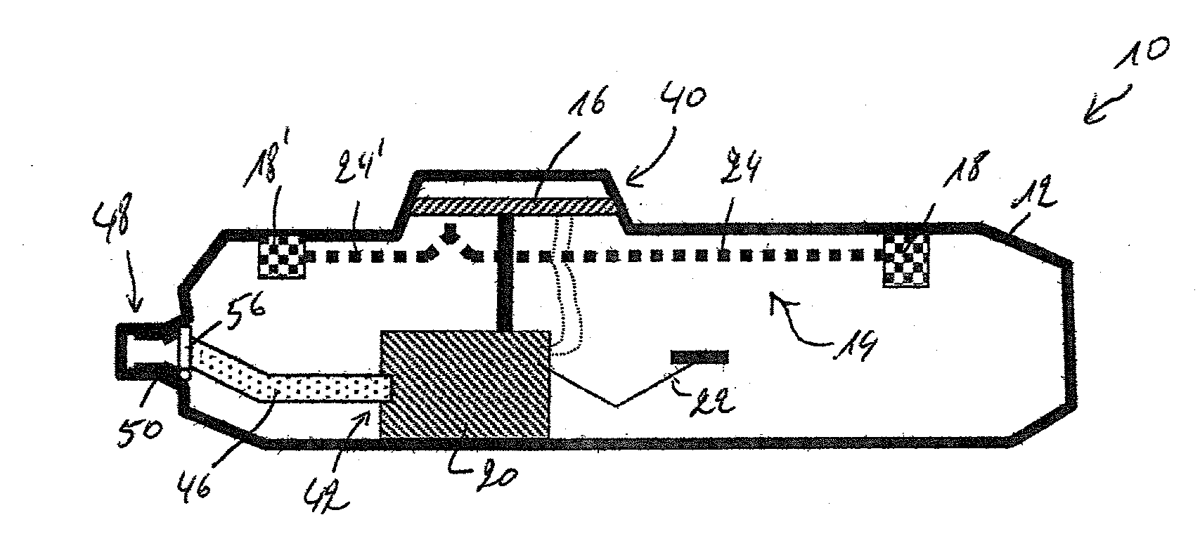
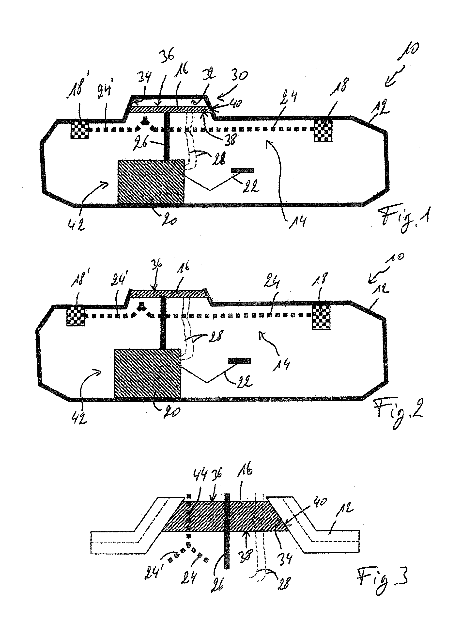
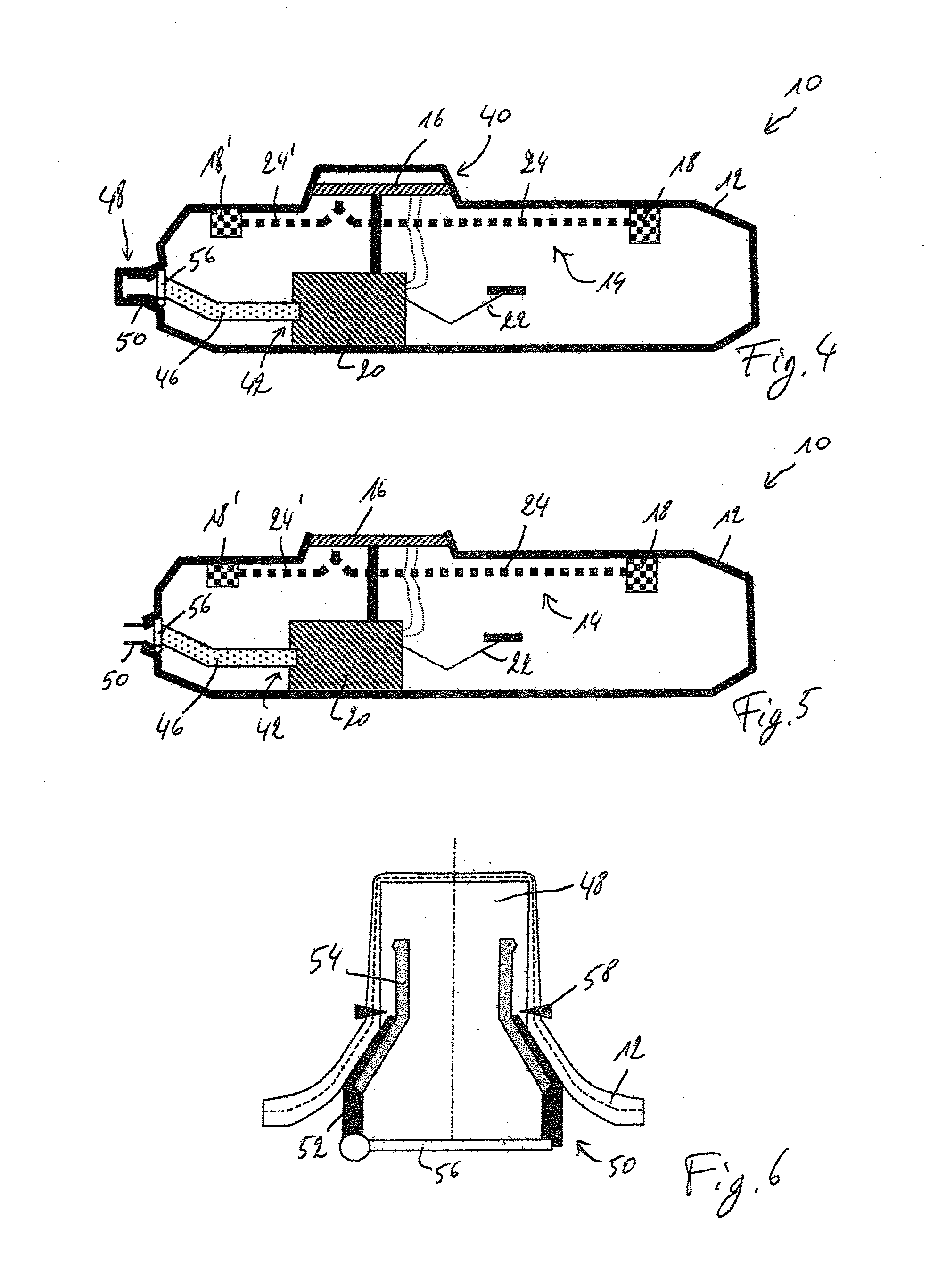
[0023]By virtue of the process according to the invention, a communication component can be mounted inside the tank rapidly, with great precision and without risks of leakage. Installation of at least one portion of the communication component after blow-molding, conventionally performed by hand, is no longer necessary, thus eliminating a significant source of errors. Similarly, due to the formation of a pocket for receiving the component, the risk of deterioration of the parison by piercing is eliminated. Finally, this pocket makes it possible to use the side wall of the component for fastening it to the parison, which in certain cases limits / facilitates machining (cutting of the skin to allow access to the component). The precise and reproducible installation of the communication component leads to a reduction in the production costs and an increase in quality of the fuel tank manufactured. After molding the tank, cutting the skin of the tank allows access to the communication component and thus makes it possible to easily obtain, through the communication component, access to the inside of the tank. It should be noted that this machining must be performed on the tank already molded with its pocket and the component in said pocket, but that this machining / cutting can be performed while the tank is till in the mold: see for instance the embodiment according to FIGS. 12-15 attached.

Problems solved by technology

Hence there may be potential sealing and permeability problems near this opening.
Furthermore, this type of closure is generally performed manually on the production line, which creates labour costs and may generate scrap due to human error.
The variants illustrated in this application require either a manual assembly step after all (with the aforementioned risks of error and handling costs), or the deformation of the parison by piercing in order to allow a portion of the component to pass through, hence a risk of damaging said parison.
Such a process is also capable of damaging said sheet / parison (indeed, the EVOH layer risks being very greatly reduced in thickness and, in an extreme case, breaking and thus no longer ensuring the impermeabilization of the filler neck) and also involves the fastening of two parts, which is complicated and costly.

Method used


Image

  • Process for manufacturing a fuel tank
  • Process for manufacturing a fuel tank
  • Process for manufacturing a fuel tank

Examples


Embodiment Construction

[0037]The term “fuel tank” is understood to mean an impermeable tank that can store fuel under various and varied environment and usage conditions. An example of this tank is that with which motor vehicles are fitted.

[0038]The fuel tank according to the invention is made of plastic.

[0039]One polymer that is often used is polyethylene. Excellent results have been obtained with high-density polyethylene (HDPE).

[0040]The wall of the tank may be composed of a single thermoplastic layer, or of two layers. One or more other possible additional layers may, advantageously, be composed of layers made of a material that is a barrier to liquids and / or gases. Preferably, the nature and thickness of the barrier layer are chosen so as to minimize the permeability of liquids and gases in contact with the internal surface of the tank. Preferably, this layer is based on a barrier resin, that is to say a resin that is impermeable to the fuel such as, for example, EVOH (a partially hydrolysed ethylene...


PUM

PropertyMeasurementUnit
shapeaaaaaaaaaa
distanceaaaaaaaaaa
permeabilityaaaaaaaaaa

Abstract

Process and device for manufacturing a plastic fuel tank equipped with at least one communication component, by molding a parison using a mold comprising two impressions and a core, said process comprising the pressing of the parison against the impressions and formation of a pocket in this parison, the communication component being fastened in this pocket by welding of at least one portion of its side wall to at least one portion of the side wall of the pocket.

Description

CROSS-REFERENCE TO RELATED APPLICATIONS[0001]The present application is a U.S. national stage entry under 35 U.S.C. §371 of International Application No. PCT / EP2010 / 050410 filed Jan. 14, 2010, which claims priority to French Application No. 09.50282, filed Jan. 19, 2009, to French Application No. 61 / 145,630, filed Jan. 19, 2009, and to French Application No. 09.03043, filed Jun. 23, 2009, these applications being herein incorporated by reference in their entirety for all purposes.TECHNICAL FIELD OF THE INVENTION[0002]The present invention relates to a process and device for manufacturing a plastic fuel tank equipped with a component.BACKGROUND[0003]Fuel tanks on board vehicles of various kinds generally have to meet sealing and permeability standards in relation to the type of use for which they are designed and the environmental requirements that they have to satisfy. At the present time, both in Europe and throughout the world, there is a substantial tightening of the requirements...

Claims


Application Information

Patent Timeline
Patent Type & Authority Applications(United States)
IPC IPC(8): B29C49/20
CPCB29C49/0047B29L2031/7172B29C49/20B29C49/22B29C2049/2008B29C2049/2073B29C2049/4617B29C2049/4623B29C2791/001B29C2791/006B29C2791/007B29C2793/0018B29C2793/009B29K2023/06B29K2023/065B29K2023/086B29K2995/0067B29C49/04B29C49/0691
Inventor CRIEL, BJORNHILL, DAVID
Owner PLASTIC OMNIUM ADVANCED INNOVATION & RES SA
Learn More