
Intrusion detection with directional sensing

a directional sensing and intrusion detection technology, applied in the field of intrusion detection with directional sensing, can solve the problems of inability to detect movement as targets, and inability to detect movement at the same tim

Active Publication Date: 2015-09-03
VSK ELECTRONICS NV
View PDF3 Cites 26 Cited by
  • Summary
  • Abstract
  • Description
  • Claims
  • Application Information

AI Technical Summary

Benefits of technology

The invention provides a method and system for detecting and tracking objects in a video image using a sensing device. The method involves defining an image detection area and a detection vector that specifies the minimum displacement and direction of displacement in the detection area. The detection vector can be a flat or three-dimensional arrow that is overlaid on the image detection area. The system can detect and track the target object by monitoring the image detection area and analyzing the changes in the detection vector. The invention can activate an alarm condition if the target object exceeds the minimum displacement in the direction of the detection vector. The technical effect of the invention is to provide a more effective method and system for detecting and tracking objects in a video image.

Problems solved by technology

One of the drawbacks of existing VMD systems is that existing systems are sensitive to all changes of intensity in the scene of interest.
If these shadows or headlight beams enter a detection area, and their movement meets the detection criteria, such movement will be wrongly detected as targets, even if the vehicles themselves are outside the detection area.
However, this detection method may also be undesirable because the trigger line must be carefully placed to ensure that all possible real target trajectories will cross the trigger line.
Furthermore, in non-ideal conditions, it is possible that the target track will be lost and restarted as the target moves through the scene.
Irrespective, the use of single or multiple trigger lines also does not prevent false alarms caused by shadows and headlight beams because these target tracks may still cross the necessary trigger lines due to the way the beams or shadow changes as the vehicle passes adjacent to the area of interest.

Method used


Image

  • Intrusion detection with directional sensing
  • Intrusion detection with directional sensing
  • Intrusion detection with directional sensing

Examples


first worked example

A First Worked Example

[0106]A working example is now described, to illustrate how an intrusion detection system may operate.

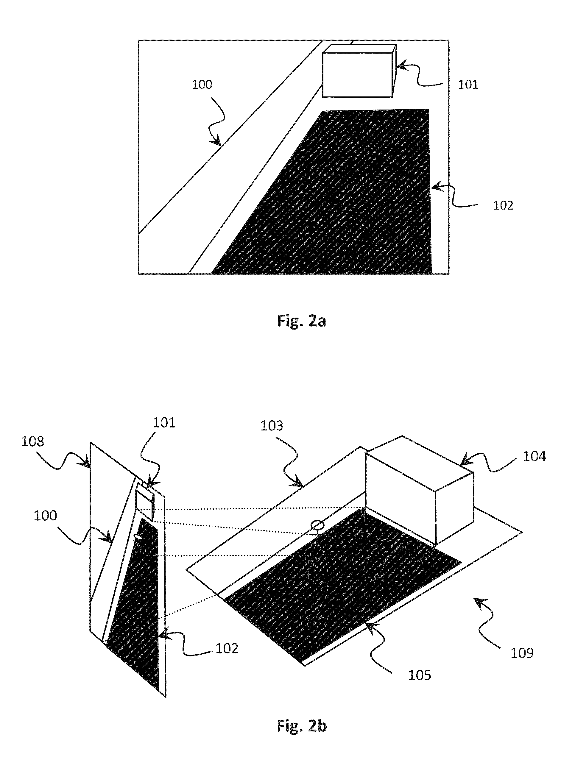
[0107]The system employs a sensing device in the form of a video camera which is used to view and monitor a real scene (in the form of a field of view) such as the three-dimensional scene depicted in FIG. 2b. The image taken by the camera is a two-dimensional projection of that three-dimensional scene onto the image plane of the camera. The camera image is then displayed on a computer monitor or display.

[0108]To use the system, an operator defines a detection area, such as 102 in FIG. 2a, through interactions with a graphical user interface on the computer monitor. This corresponds to a virtual planar detection area in the three-dimensional scene, such as 105 in FIG. 2b.

[0109]There are many ways to calibrate the system, but for illustrative purposes, calibration occurs while a person walks around every part of the three-dimensional planar detection area 105, a...

second worked example

A Second Worked Example

[0114]FIG. 7 shows how the entry and exit from a detection area can be determined. In this Figure, the two-dimensional image 600 consists of picture elements (pixels) 601, and the detection area is defined by the shaded pixels 602. The path 603 of an object passes through the detection area 602, entering it at a first pixel 604 and exiting it at a final pixel 605. The three-dimensional coordinates of pixels 604 and 605 can be computed from the two-dimensional positions in the image (as discussed in detail above), and the three-dimensional coordinates may then be used to determine the component of the three-dimensional distance traveled in the direction specified. Furthermore, any or all other pixels 606 along the path inside the detection area may be similarly transformed and considered. This is particularly important if the path is not straight.

[0115]If the detection area 602 above is narrow enough where the object path passes through, then the pixels 604 and...


PUM


Abstract

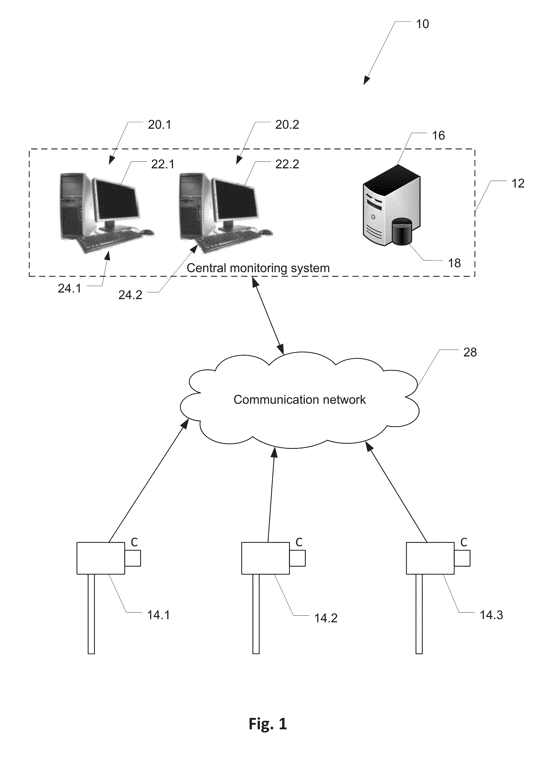
A method and system of intrusion detection, which includes displaying sensing device output data as one or more images of a field of view of a sensing device (14.1, 14.2, 14.3). Through interaction with a graphical user interface: a user input to define and display an image detection area in relation to the one or more images of the field of view is received, wherein the image detection area is correlated to a detection area to be monitored by the sensing device (14.1, 14.2, 14.3) for intrusion detection. One or more user inputs that define a detection vector in the image detection area are received, the detection vector specifying a predetermined minimum displacement and direction of displacement in the field of view to be monitored. A graphical representation of the detection vector may be displayed on the image detection area. The method further includes detecting a target object and tracking the target object at least partially through the detection area and determining whether the progressive displacement of the target object has a component which exceeds the minimum displacement in the direction of the detection vector.

Description

CLAIM OF PRIORITY[0001]This application claims the benefit of priority of U.S. Provisional Patent Application Ser. No. 61 / 947,335, filed on Mar. 3, 2014, and the benefit of priority of Australia Patent Application No. 2014901121, filed on Mar. 28, 2014, the benefit of priority of which is claimed hereby, and which are incorporated by reference herein in their entirety.FIELD OF THE INVENTION[0002]The present invention generally relates to a security system for detecting intruders at a site being monitored. More specifically, the invention relates to a system and method of directional detection employing video capture.BACKGROUND OF THE INVENTION[0003]Video motion detection (VMD) is frequently used in the current security industry for detecting intruders entering a site, with predetermined scenes of interest. VMD is performed by computer software on a sequence of digital images captured by a video camera that is monitoring a particular scene of interest. Each image in the sequence is c...

Claims


Application Information

Patent Timeline
IPC IPC(8): H04N7/18H04N5/232
CPCH04N5/23216H04N7/18G08B13/19613H04N7/183G08B13/19682H04N7/188G08B13/19656H04N7/181H04N23/62
Inventor NAYLOR, MATTHEWTILKIN, JORGMAELBRANCKE, GERDYCORNEZ, PHILIPPEDE LELLIS, DOMENICOROELS, LUCPIGNATTA, PHILIPPEBAS, ALIPALFI, ENIKO
Owner VSK ELECTRONICS NV
Learn More