Ion generation device

a generation device and ionization technology, applied in the direction of corona discharge, heating type, separation process, etc., can solve the problems of uncontrollable and undesirable ozone, increased energy consumed during the operation of ionization tubes, and high replacement costs of such tubes

Active Publication Date: 2015-09-10
GLOBAL PLASMA SOLUTIONS INC
View PDF14 Cites 9 Cited by
  • Summary
  • Abstract
  • Description
  • Claims
  • Application Information

AI Technical Summary

Problems solved by technology

Glass by its very nature has a fragile structure and is prone to breaking The glass tube in an ionization tube also produces a corona discharge, which minimizes the effect of the ionization tube and increases the amount of energy consumed during operation of ionization tube.
The glass tube breaks down over time and must be replaced by the user and the replacement cost for such a tube is high.
Additionally, the glass tube requires a voltage high enough to break down the dielectric strength of the glass, and during the break down process, a corona discharge is created, thus causing uncontrolled and undesirable ozone.

Method used


Image

  • Ion generation device
  • Ion generation device
  • Ion generation device

Examples


Embodiment Construction

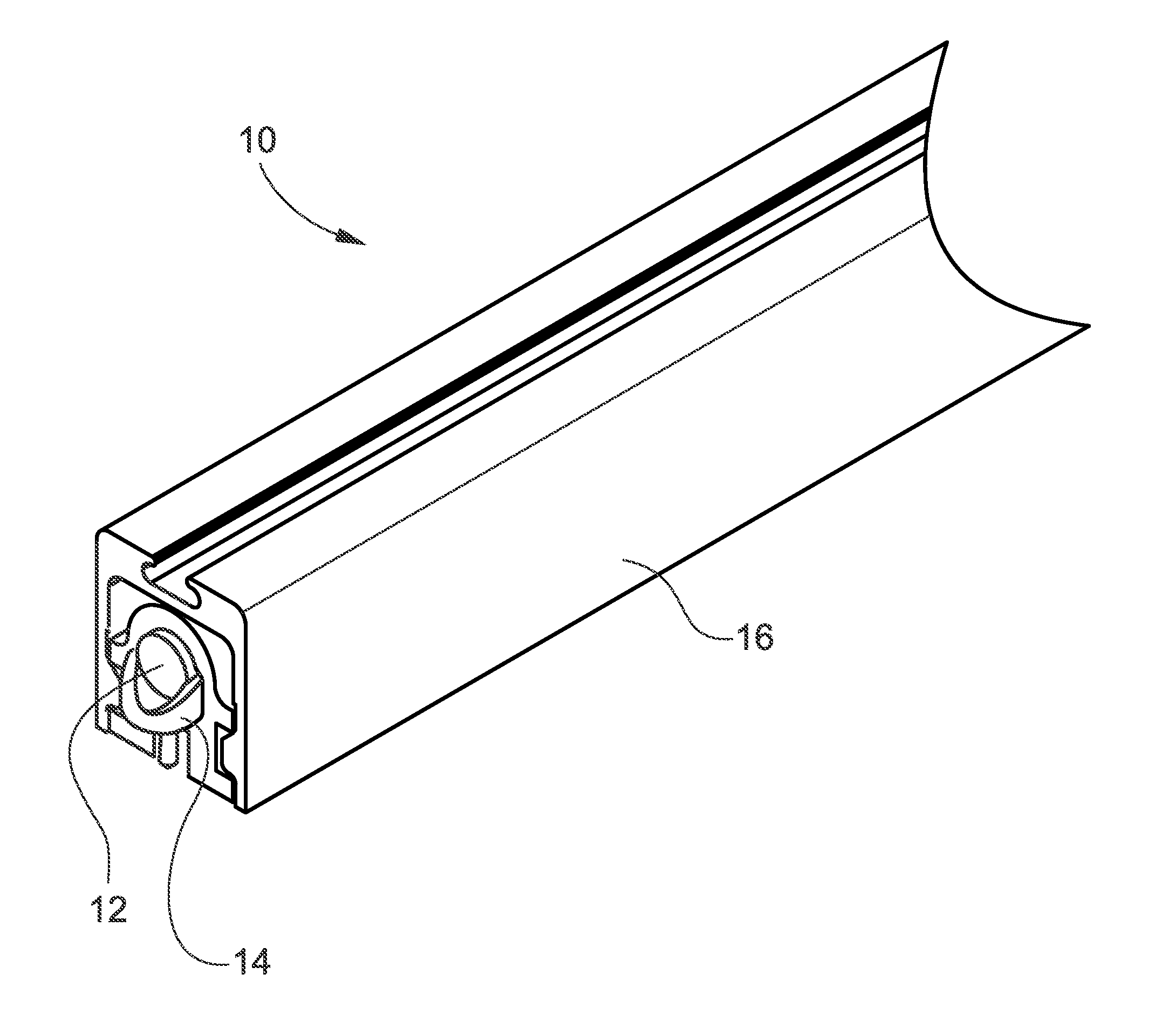
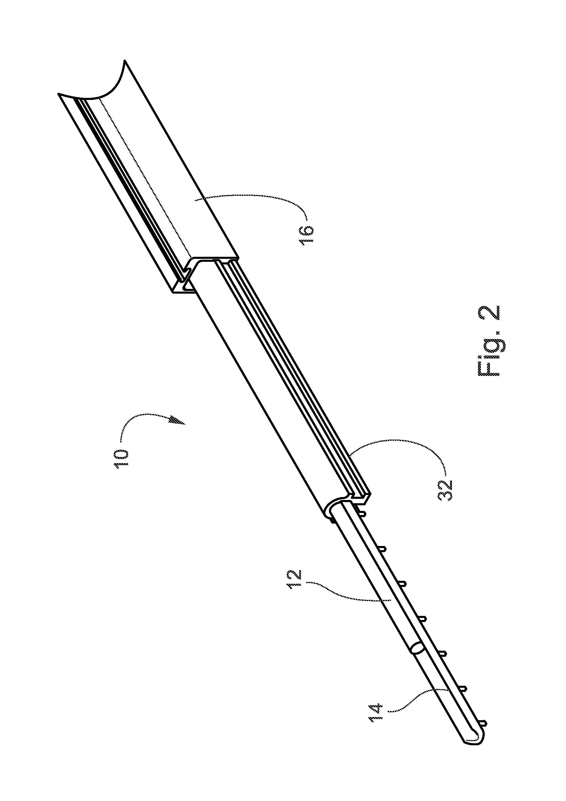
[0035]Referring now specifically to the drawings, an ion generation device is illustrated in FIGS. 1, 2, and 3 and is shown generally at reference numeral 10. The ion generation device 10 generally comprises a power supply 12, a conductive portion 14, and a housing 16. The power supply 12 spans substantially the length of the ion generation device 10 and carries electrical current. The conductive portion 14 also spans substantially the length of the ion generation device 10 and is disposed in close proximity to the power supply 12. The housing 16 contains a cavity 18 for retaining the power supply 12 and a conductive portion 14. Preferably, the housing 16 contains a back portion 20 and two side portions (22, 24) each extending generally perpendicularly from the back portion 20. The cavity 18 is located within the back portion 20 and two side portions (22, 24) and having an opening opposite the back portion 20. The cavity 18 is designed to house, retain, and protect the power supply ...


PUM

PropertyMeasurementUnit
lengthaaaaaaaaaa
diameteraaaaaaaaaa
lengthaaaaaaaaaa

Abstract

The present invention provides methods and systems for an ion generation device that includes an elongate housing having a back portion and a pair of side portions extending from the back portion and forming a cavity therein. A conductive portion is disposed within the cavity and connected to a power supply for providing power to the conductive portion. A plurality of tines are engaged to the conductive portion.

Description

CROSS REFERENCE TO RELATED PATENT APPLICATION[0001]The current application is a divisional of co-pending U.S. patent application Ser. No. 13 / 918,282 filed Jun. 14, 2013, and entitled “ION GENERATION DEVICE”, which in turn claims the benefit of the earlier priority filing of provisional application Ser. No. 61 / 660,301 filed Jun. 15, 2012.FIELD OF THE INVENTION[0002]The present invention relates generally to an ion generation device and more generally relates to a ion generation device that includes tines composed of polypropylene impregnated with carbon for discharging ions within the proximate area of the device.BACKGROUND OF THE INVENTION[0003]Current ionization tubes utilize a cathode that is completely surrounded by a glass tube. The inside of the glass tube contains a wire mesh that serves as an anode. Glass by its very nature has a fragile structure and is prone to breaking The glass tube in an ionization tube also produces a corona discharge, which minimizes the effect of the ...

Claims


Application Information

Patent Timeline
Patent Type & Authority Applications(United States)
IPC IPC(8): F24F3/16H01J37/16B03C3/02H01J37/08H01T23/00B03C3/41
CPCF24F3/166H01T23/00H01J37/16B03C3/02H01J37/08B03C3/41B01D53/323B01D2257/90B01D2259/4508B01D2259/818H01T19/04B03C2201/10Y10T29/49117Y10T29/49169F24F8/30F24F8/192A61L2/14H01J27/02A61L9/22B03C3/04B03C3/82H01J27/022
Inventor WADDELL, CHARLES HOUSTON
Owner GLOBAL PLASMA SOLUTIONS INC
Why Eureka
Try Eureka