
Image processing apparatus and image processing method

a technology of image processing and image processing, applied in the field of image processing equipment and image processing methods, can solve the problems of low-density images being lost, image within the read-in image becomes difficult to see, image quality deterioration, etc., and achieves the effect of reducing show-through

Active Publication Date: 2015-09-10
CANON KK
View PDF9 Cites 21 Cited by
  • Summary
  • Abstract
  • Description
  • Claims
  • Application Information

AI Technical Summary

Benefits of technology

The present invention is about an image processing apparatus that can reduce show-through in an image taken by an original. The apparatus includes a storage unit that stores index values for variations in signal values, a first obtainment unit that obtains a degree of variation of signal values within a predetermined size of a region of interest, a second obtainment unit that obtains a value indicating the brightness of the region of interest, and a determination unit that uses the degree of variation and the brightness value to determine an amount of correction needed to adjust the value of a pixel of interest. A correction unit then uses the determined correction amount to adjust the value of the pixel of interest. This invention can improve image quality by reducing show-through and enhancing clarity.

Problems solved by technology

In copying machines, multi-function peripherals, and the like there are cases in which a problem known as show-through occurs in a case where an original is read using an image reading apparatus (scanner) installed therein.
When show-through occurs, an image within the read-in image becomes difficult to see, i.e. the quality of the image deteriorates.
For this reason, there is a possibility that low-density images will be lost.

Method used


Image

  • Image processing apparatus and image processing method
  • Image processing apparatus and image processing method
  • Image processing apparatus and image processing method

Examples


first embodiment

[0033]Explanation is given below with an example of a copying machine 1000 as a first embodiment of an image processing apparatus according to the present invention.

[0034]

[0035]

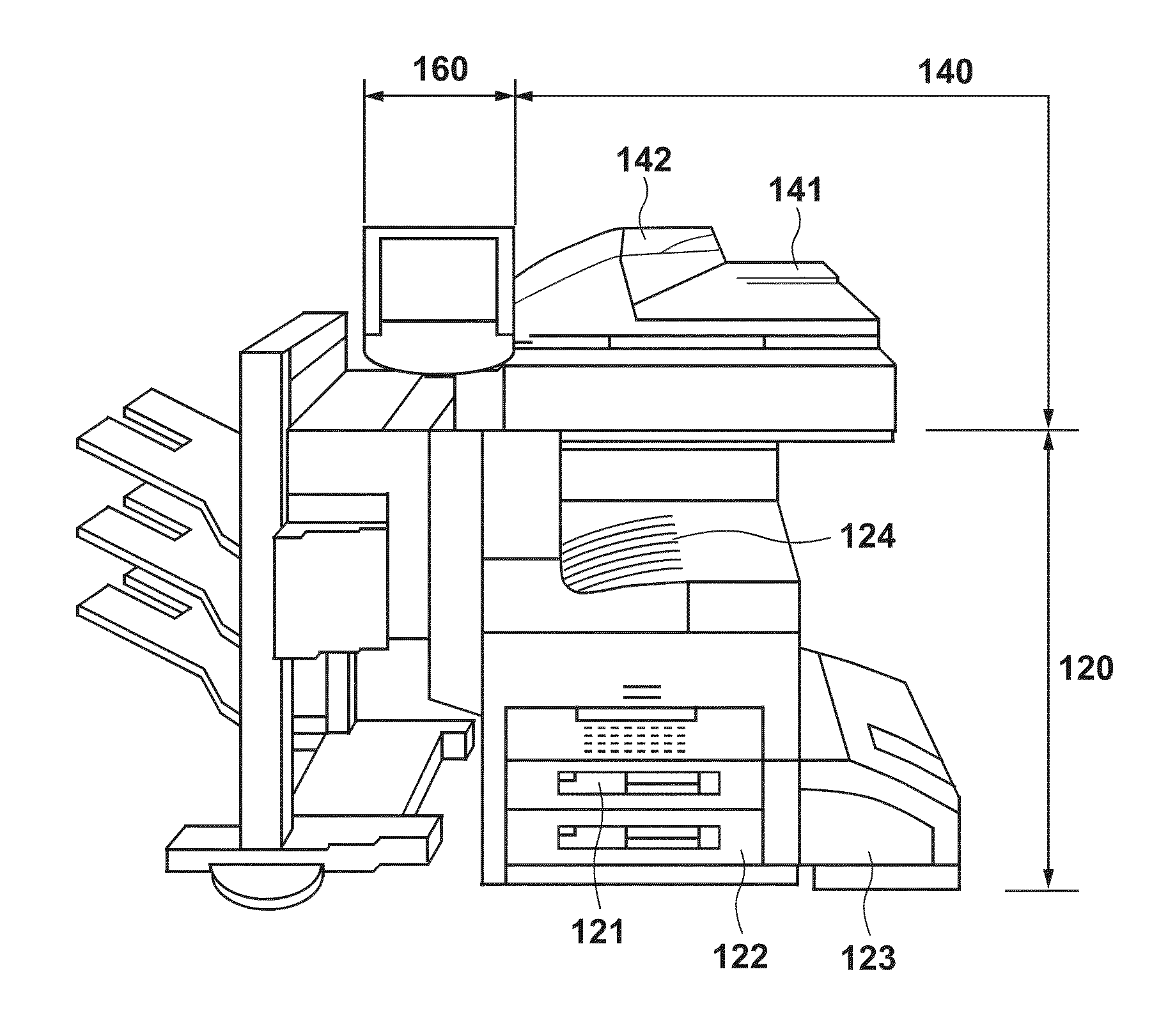
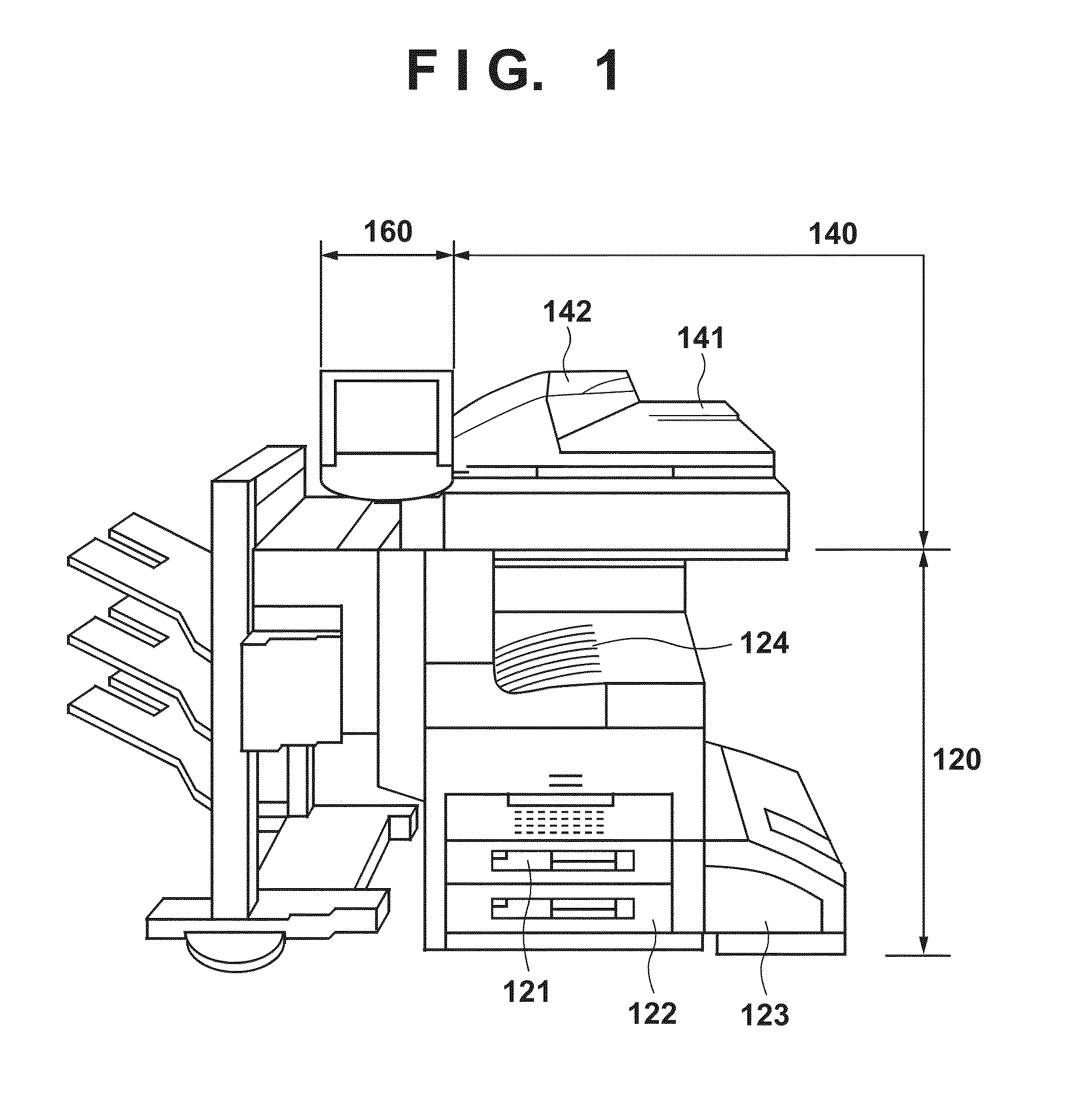
[0036]FIG. 1 is a view for showing explanatorily an outer appearance of a copying machine 1000 according to a first embodiment. The copying machine 1000, in accordance with a copy instruction received from a user via an operation unit 160 reads, by a scanner unit 140, an original set in an original feeder 141, performs by a printer 120 image forming on a sheet of the read in image, and outputs.

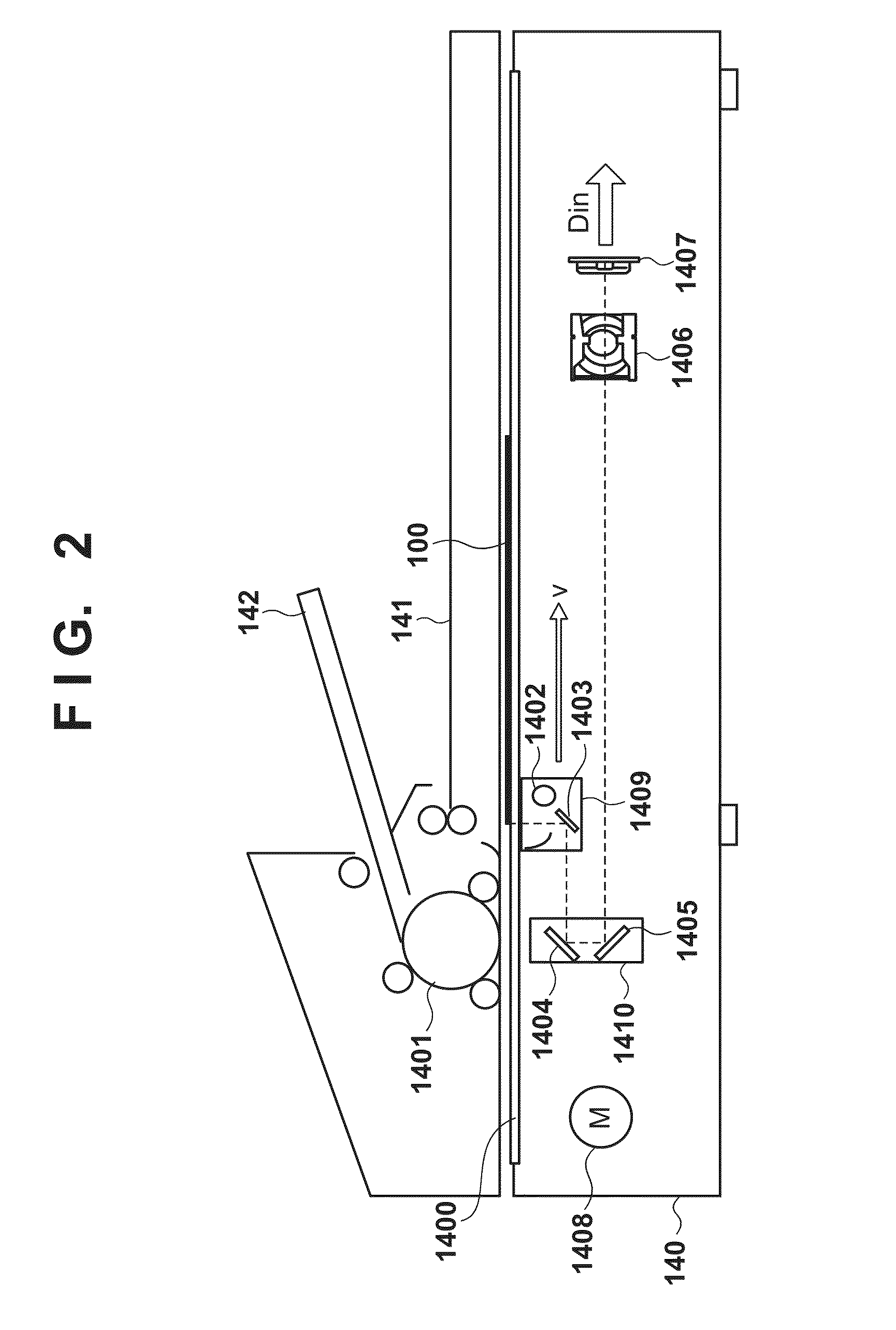
[0037]The scanner unit 140, which is an image reading unit, by inputting reflected light obtained by exposure scanning an image on an original by a light emission from an illumination lamp into a linear image sensor (CCD sensor), converts information of the image into an electrical signal. The scanner unit 140 further converts the electrical signal into a luminance signal comprising the colors R, G, and B, and outputs t...

second embodiment

[0109]In the second embodiment, a method and a configuration for executing generation of the show-through correction information that becomes the index for correcting show-through and show-through correction processing in parallel are described. Therefore, while in the first embodiment a processing delay occurs due to the configuration in which the show-through correction processing is executed after the generation of the show-through correction information is completed, the processing delay is reduced by performing parallel processing of the two processes.

[0110]In the second embodiment the internal configuration of the scanner image processing unit 2400 and the processing flow pertaining to the show-through correction are different to those of the first embodiment. However, the outer appearance of the copying machine, the configuration of the scanner unit 140, and the configuration of the controller 200 are similar to those of the first embodiment. Below, detailed explanation will ...

third embodiment

[0134]In the third embodiment, explanation will be given for an example in which show-through correction information that becomes the index for correcting show-through is generated in advance and is stored in a storage unit. In the third embodiment the internal configuration of the scanner image processing unit 2400 (in particular, the show-through correction processing unit) and the processing flow pertaining to the show-through correction are different to the second embodiment. However, the outer appearance of the copying machine, the configuration of the scanner unit 140, and the configuration of the controller 200 are similar to those of the first and second embodiments. Below, detailed explanation will be given for the third embodiment with a focus on portions that are different to the second embodiment.

[0135]

[0136]FIG. 15 is a block diagram for showing a configuration of a show-through correction processing unit 2460 in the third embodiment. The arrangement of the blocks withi...


PUM


Abstract

For preferably reducing show-through in an image obtained by reading an original, an image processing apparatus, stores an index value for each of a plurality of mutually differing degrees of variation; obtains a degree of variation of signal values included in a region of interest of a predetermined size including a pixel of interest included in image data; obtains a value indicating a brightness of the region of interest; determines an amount of correction of a value of the pixel of interest using the obtained value and an index value corresponding to the obtained degree of variation; and corrects the value of the pixel of interest using the determined amount of correction.

Description

BACKGROUND OF THE INVENTION[0001]1. Field of the Invention[0002]The present invention relates to an image processing technique for correcting an image obtained by reading an original.[0003]2. Description of the Related Art[0004]In copying machines, multi-function peripherals, and the like there are cases in which a problem known as show-through occurs in a case where an original is read using an image reading apparatus (scanner) installed therein. Show-through is something in which an image on the other surface (a back surface) of the original appears in the read-in image, in a case where a surface of the original (a front surface) is read by an image reading apparatus. Thus, this mainly occurs in cases in which both surfaces (front surface and back surface) of the original that is read by the image reading apparatus have some kind of image printed on them. Show-through tends to occur in cases where a high density image exists on the back surface. Also, this occurs due to the light ...

Claims


Application Information

Patent Timeline
Patent Type & Authority Applications(United States)
IPC IPC(8): H04N1/409H04N1/40H04N1/407G06T7/40G06T5/40
CPCH04N1/4095G06T7/408H04N1/40093H04N1/4072G06T5/40G06T7/40H04N1/40H04N1/407H04N1/409G06T5/90H04N1/4092H04N1/58
Inventor IKARI, DAIKI
Owner CANON KK
Learn More