Light emitting apparatus

Active Publication Date: 2015-09-17
CITIZEN WATCH CO LTD +1
View PDF8 Cites 32 Cited by
  • Summary
  • Abstract
  • Description
  • Claims
  • Application Information

AI Technical Summary

Benefits of technology

[0023]The above light emitting apparatus causes no lateral light leakage, enabl

Problems solved by technology

As the results, the production man-hour becomes high, and gaps may be generated below the reflection frame due to the concave-convex shape formed by a wiring electrode or the like, on the circuit substrate.
The gaps cause light leakage of l

Method used


Image

  • Light emitting apparatus
  • Light emitting apparatus
  • Light emitting apparatus

Examples


Embodiment Construction

[0044]Hereinafter, with reference to the drawings, exemplary embodiments of the light emitting apparatus will be described. It should be noted that the technical scope of the present invention is not limited to the following embodiments, but covers the invention described in the claims and its equivalent. In the explanation of the drawings, the same symbols are attached to the same or corresponding elements, and duplicated explanation is omitted. The scale of members is appropriately changed for explanation.

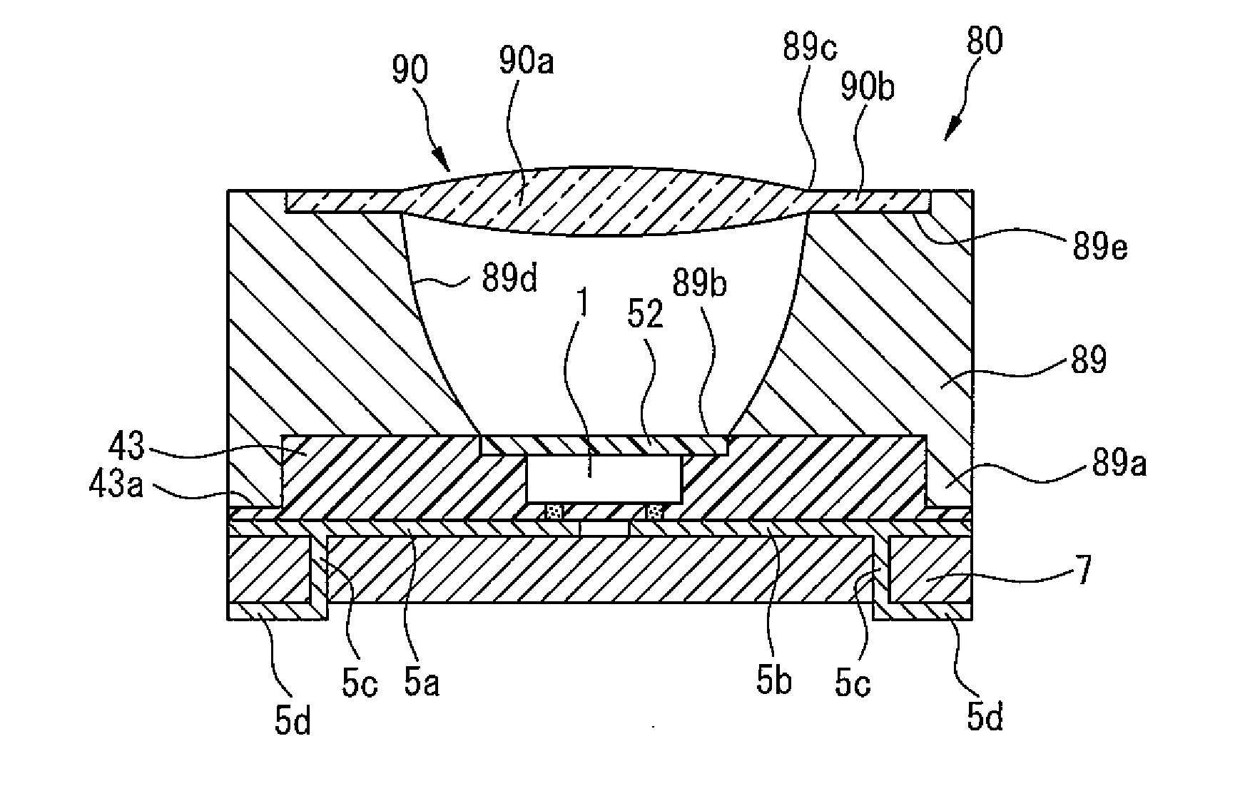
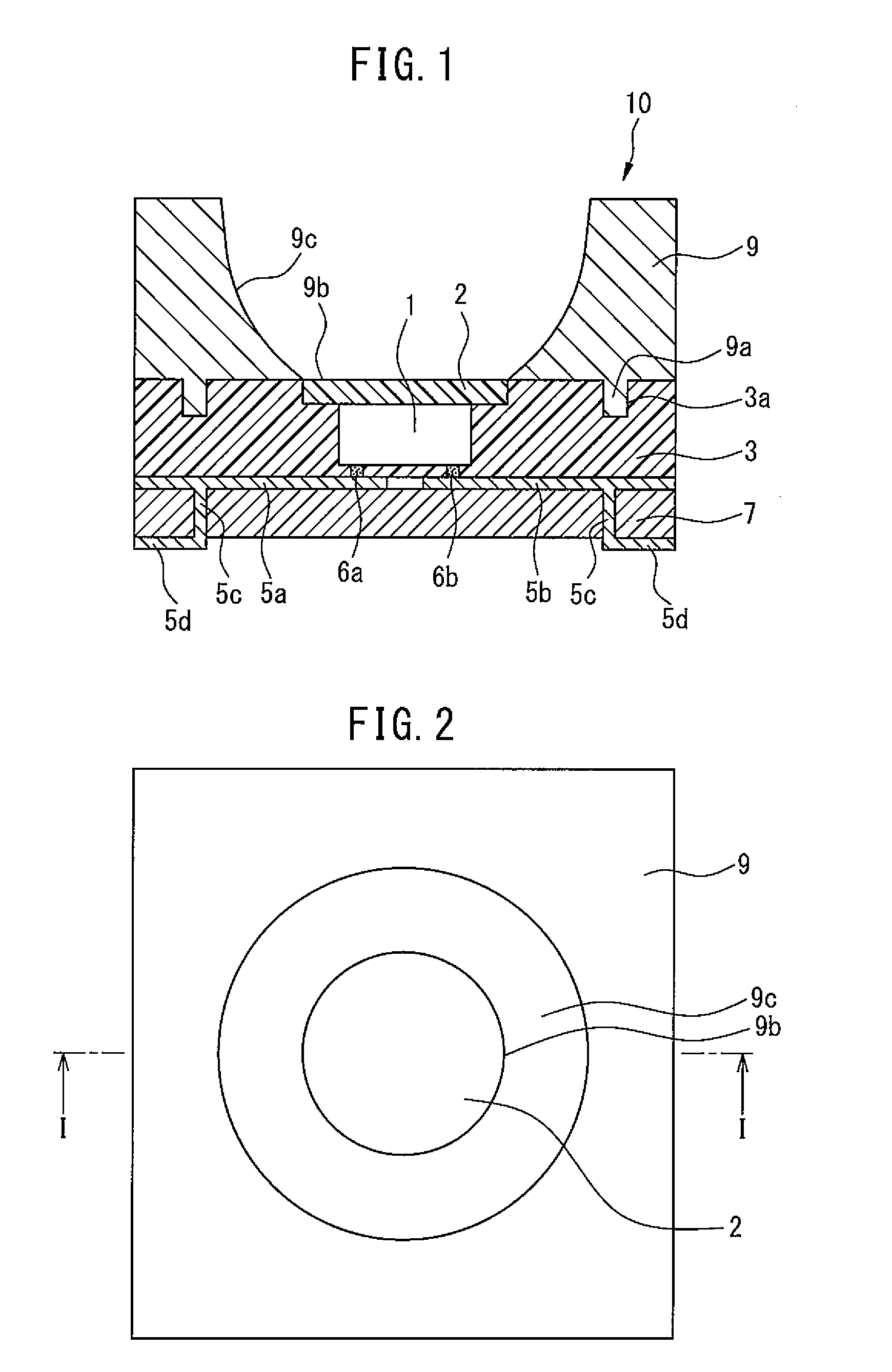
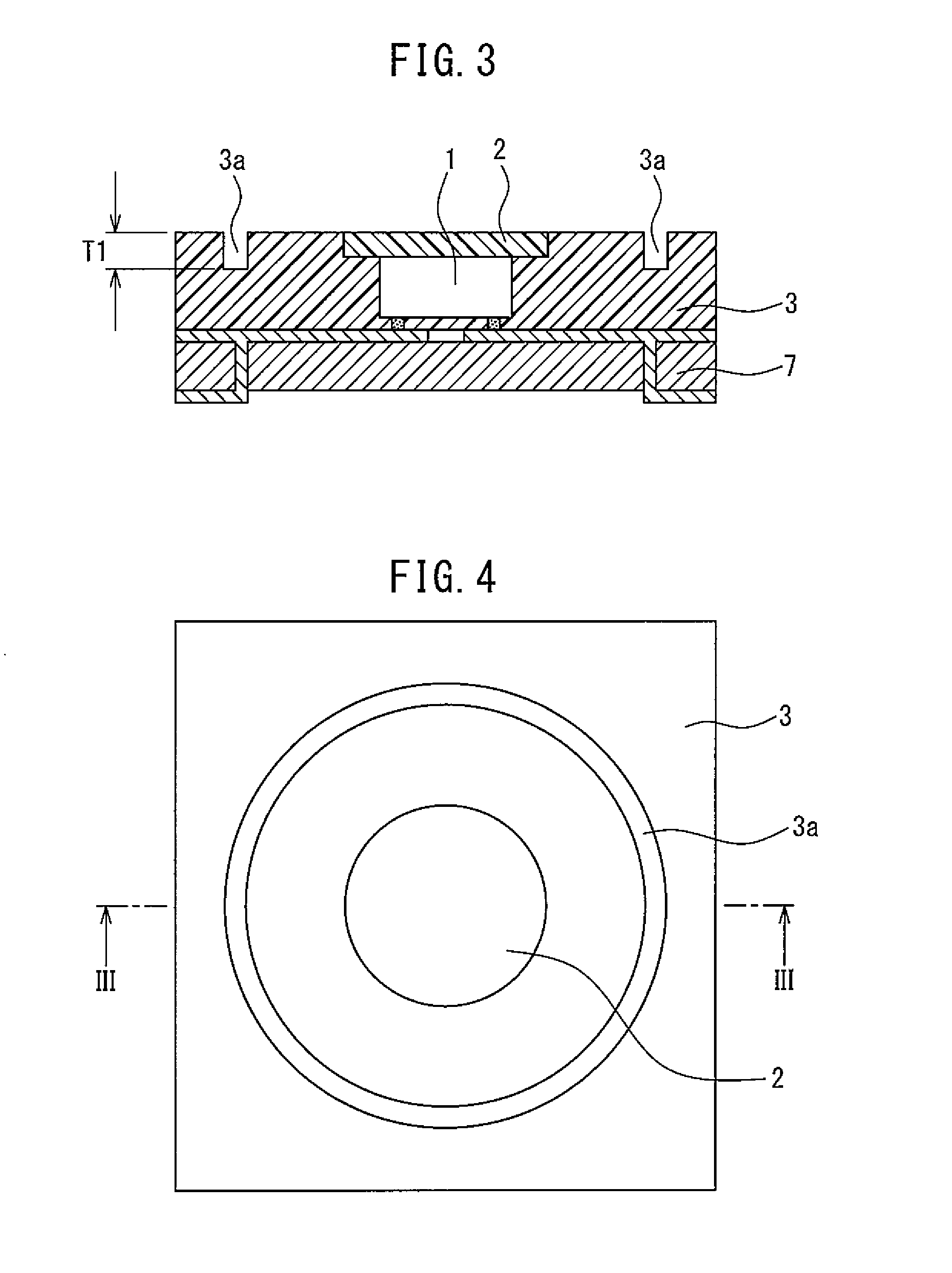
[0045]FIGS. 1 and 2 are respectively a cross-sectional view and a top view of a light emitting apparatus 10. FIG. 1 depicts a cross-section along the line I-I in FIG. 2. As depicted in FIG. 1, the light emitting apparatus 10 includes a circuit substrate 7. Wiring electrodes 5a and 5b are provided on the upper side of the circuit substrate 7, and power electrodes 5d are provided on the back side of the circuit substrate 7. On the wiring electrodes 5a and 5b, an LED device 1 is fli...


PUM


Abstract

Provided is a light emitting apparatus that causes no lateral light leakage, enables easy assembly, and allows free selection of the shape of a reflection frame. The light emitting apparatus includes an LED device which is flip-chip mounted on a substrate, a phosphor layer placed on a light emitting surface of the LED device, a reflective resin having a recessed portion formed on the upper surface thereof, the reflective resin covering the side surface of the LED device and the side surface of the phosphor layer, and a reflection frame having a protruded portion formed on the lower surface thereof, the reflection frame being fixed on or above the phosphor layer and the reflective resin by engaging the protruded portion with the recessed portion of the reflective resin.

Description

CROSS REFERENCE TO RELATED APPLICATIONS[0001]This application is a new U.S. patent application that claims benefit of JP 2014-051040, filed on Mar. 14, 2014, and JP 2014-052117, filed on Mar. 14, 2014. The entire contents of JP 2014-051040 and JP 2014-052117 are hereby incorporated by reference.BACKGROUND[0002]1. Technical Field[0003]The present invention relates to a light emitting apparatus with a light emitting diode (LED) device as a light emitting source.[0004]2. Related Art[0005]Since an LED device is a semiconductor device, it has a longer operating life and superior operating characteristics, is small-sized, has high light emission efficiency, and exhibits a bright luminescent color. As the results, an LED device has been widely used recently as a backlight for a color display apparatus, a flashlight apparatus, an illumination, or the like.[0006]Among others, a reflection-frame-type light emitting apparatus has recently been proposed, in which the surroundings of an LED devi...

Claims


Application Information

Patent Timeline
IPC IPC(8): H01L33/48H01L33/54F21V13/14H01L33/62F21K99/00H01L33/50H01L33/60
CPCH01L33/486H01L33/505H01L33/507H01L33/54F21Y2101/02H01L33/62F21K9/54F21K9/56F21V13/14H01L33/60H01L33/56H01L2933/0033H01L2933/005H01L2924/181H01L2224/16225H01L2924/00012F21K9/62F21K9/64F21Y2115/10
Inventor WATANABE, YUSUKE
Owner CITIZEN WATCH CO LTD
Why Eureka
Try Eureka