Supercharge Your Innovation With Domain-Expert AI Agents!

Motorization unit for manual stage, and manual stage having motorization unit

a technology of motorization unit and manual stage, which is applied in the direction of electrical equipment, dynamo-electric machines, instruments, etc., can solve the problems of inability to easily replace manual fine operation of control knobs, and need more expensive control mechanisms or control softwar

Inactive Publication Date: 2015-09-17
MIRUC OPTICAL CO LTD
View PDF3 Cites 3 Cited by
  • Summary
  • Abstract
  • Description
  • Claims
  • Application Information

AI Technical Summary

Benefits of technology

The present invention provides a motorization unit for a manual stage that allows for both automatic and manual operation. This is achieved by adding a simplified mechanism to a prior-art manual stage of moving a sliding component by manual rotation of a control knob. Additionally, the motorization unit enables manual fine adjustment of the stage.

Problems solved by technology

In an automatic stage in which a stage and a rotationary driving mechanism such as a motor are integrated or an electric stage, since an automating device such as a motor is embedded in the stage, movement of a sliding component is limited to be performed by automatic operation.
Thus, it is inconvenient in some cases for users who are used to a manual stage.
For example, it is inconvenient when fine movement is required for positional adjustment.
In such a case, manual adjustment is more preferable, and automatic operation cannot easily replace a manual fine operation of a control knob.
Moreover, if the manual fine adjustment is to be realized by automation (or electrical driving), it involves a problem that a more expensive control mechanism or control software will be needed.
Moreover, since users of the stage cannot attach the integrated automatic stage to an existing manual stage, it involves a problem that they should newly purchase automatic stages.
Furthermore, the mechanism for preventing the co-rotation should be a mechanism which can be removably attached to the manual stage easily, which is a problem.

Method used


Image

  • Motorization unit for manual stage, and manual stage having motorization unit
  • Motorization unit for manual stage, and manual stage having motorization unit
  • Motorization unit for manual stage, and manual stage having motorization unit

Examples


first embodiment

Configuration of Motorization Unit for Manual Stage

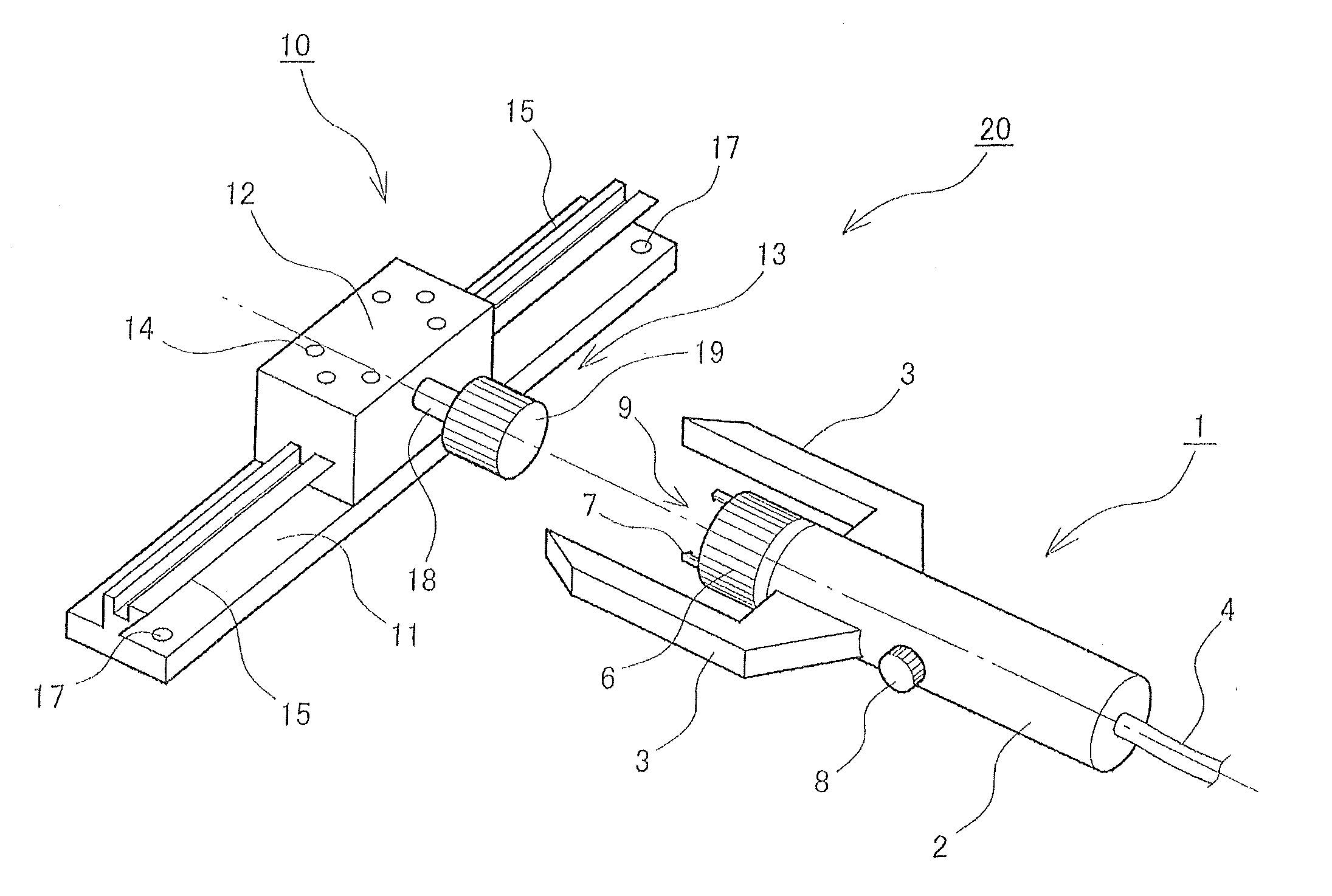
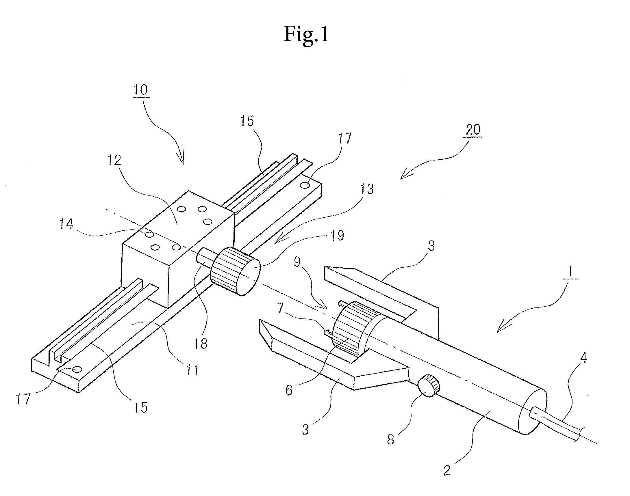
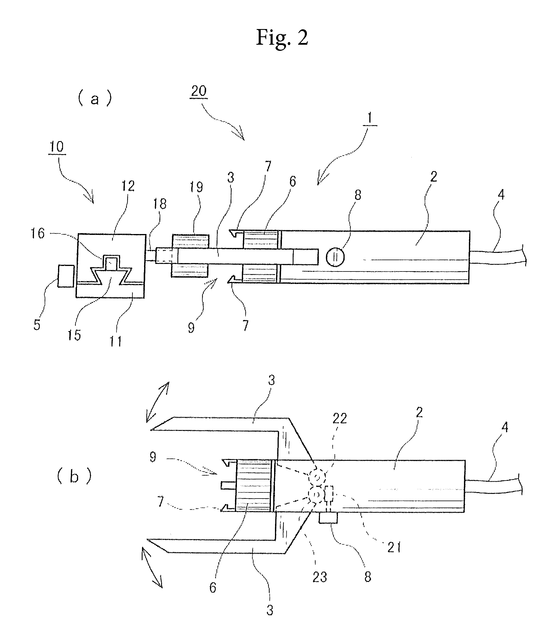
[0102]A first embodiment of a motorization unit 1 for a manual stage according to the present invention will be described below in detail with reference to the attached drawings. FIG. 1 illustrates a perspective view of a schematic configuration of the first embodiment of the motorization unit 1 for a manual stage. The motorization unit 1 for a manual stage is attached to a manual stage 10, and a function of an automatic stage is exerted in the manual stage 10. Further,FIG. 2 illustrates a side view of the motorization unit 1 for a manual stage in FIG. 1.

[0103]In the manual stage 10, a sliding component 12 is coupled to a fixed component 11 via a driving mechanism such as a rack-and-pinion type, a feed-screw type and the like, for example. FIG. 1 illustrates a case in which the manual stage is of the rack-and-pinion type in which the a rack 15 and a pinion gear 16 (see FIG. 2) are meshed with each other and slide, but other manual s...

second embodiment

Configuration of the Motorization Unit for Manual Stage

[0109]A second embodiment of a motorization unit 30 for a manual stage according to the present invention will be described below in detail with reference to the attached drawings. FIG. 3 illustrates a schematic configuration of the second embodiment of the motorization unit 30 for a manual stage in a perspective view. The motorization unit 30 for a manual stage is attached to the manual stage 10, and the function of the automatic stage is exerted in the manual stage 10. Moreover, FIG. 4 illustrates a plan view of the motorization unit 30 for a manual stage in FIG. 3. Furthermore, FIG. 5 illustrates a side view of the motorization unit 30 for a manual stage in FIG. 4.

[0110]In the manual stage 10, the sliding component 31 is coupled to the fixed component 44 via a driving mechanism such as a rack-and-pinion, a feed screw and the like, for example. FIG. 3 illustrates a case of the rack-and-pinion type manual stage in which a rack ...

third embodiment

Configuration of Motorization Unit for Manual Stage

[0126]A third embodiment of a motorization unit 200 for a manual stage according to the present invention will be described below in detail with reference to the attached drawings. FIG. 17 illustrates a schematic configuration of the third embodiment of the motorization unit 200 for a manual stage in a perspective view. Moreover, FIG. 18 illustrates configurations of a rotation preventing jig 203, a motor connecting portion 208, and a geared motor 248 of the motorization unit 200 for a manual stage in FIG. 17. Moreover, FIG. 19 illustrates a connecting method between a manual stage 210 and the rotation preventing jig 203 in a perspective view. Furthermore, FIG. 20 illustrates a part of a manual stage 220 with the motorization unit in a sectional view. The motorization unit 200 for a manual stage is attached to the manual stage 210, and a function of the automatic stage is exerted in the manual stage 210.

[0127]In the manual stage 210...


PUM


Abstract

By removably attaching a simplified mechanism to a prior-art stage for moving a sliding component by manual rotation of a control knob, an automatic mode and a manual mode can be made selectable and moreover, a motorization unit for a manual stage capable of fine adjustment by manual operation and a manual stage with the motorization unit is provided.A motorization unit for a manual stage is provided with a clamp for preventing co-rotation by sandwiching a sliding component or a fixed component of a manual stage, a coupling coupled to a control knob while holding substantial coaxiality with a control knob shaft, a coupling claw for gripping a knob portion, and a motor for rotating the coupling, either one of manual operation and automatic operation being selected by removal from / attachment to the manual stage, and constitutes a manual stage with the motorization unit by being equipped to the manual stage.

Description

TECHNICAL FIELD[0001]The present invention relates to a motorization unit for manual stage and manual stage having motorization unit, and particularly to a motorization unit which is attached to a manual stage for manually moving a sliding component or a fixed component and automatically moves the sliding component or the fixed component and a manual stage equipped with this motorization unit.BACKGROUND ART[0002]For example, electric / electronic devices such as a CCD camera and a sensor, optical devices such as a lens and a microscope, and illumination devices such as an LED, need positional adjustment for positioning or focusing when attaching them in some cases. Moreover, after attaching them, their positions need to be further adjusted finely in some cases. The above-described electric / electronic devices, optical devices, illumination devices and the like are installed on a mechanical element called a “stage” in general for positional adjustment or fine adjustment. In this specifi...

Claims


Application Information

Patent Timeline
Patent Type & Authority Applications(United States)
IPC IPC(8): H02K7/00H02K7/14
CPCH02K7/14H02K7/003G12B5/00
Inventor MURAMATSU, HIROAKI
Owner MIRUC OPTICAL CO LTD
Features
  • R&D
  • Intellectual Property
  • Life Sciences
  • Materials
  • Tech Scout
  • Unparalleled Data Quality
  • Higher Quality Content
  • 60% Fewer Hallucinations
Learn More