Chair chassis and chair having the same

a chair chassis and chair technology, applied in the field of chair chassis and chair, can solve the problems of more parts being required for calibration purposes, difficulty in accurately adapting to the user's needs, and excessive light or excessively heavy pressure, so as to avoid or significantly reduce the friction of the backrest, reduce the leaning back, and reduce the rearward pressure

Inactive Publication Date: 2015-10-01
SHANTOU LISHI FURNITURE
View PDF10 Cites 4 Cited by
  • Summary
  • Abstract
  • Description
  • Claims
  • Application Information

AI Technical Summary

Benefits of technology

[0008]According to the present application, when a chair user sits on the chair and leans back against the chair backrest, the movable support member is subject to weight pressure of the user transferred by the seat bearing plate and resistance of the elastic member (equal to an elastic restoring force) on the one hand, and on the other hand, is subject to rearward pressure transferred by the backrest, their torque generates balance by taking a lower end of the movable support member pivotally connected to the main tray base as a fulcrum, if the weight pressure applied by a person is greater, balance is generated when the rearward pressure against the backrest is greater, on the contrary, if the weight pressure applied by a person is smaller, balance can be generated when the rearward pressure against the backrest is smaller. Therefore, in order to adjust rearward angle and position of the backrest, persons with different weights need to apply rearward pressure to the backrest which automatically adapts according to weight pressure applied by the persons and degree of resistance of the elastic member, and this just meets different needs of users with different weights (generally, it is more comfortable for persons with greater weight when the reactive force of the backrest that the back is subject to in the rearward process is greater, while it is more comfortable for persons with less weight when the reactive force is less), so that the user may adjust a rearward angle of the backrest with ease according to his own weight, and control the backrest to stay at an angle most suitable for the pressure produced on the back, so that a condition that the pressure of the backrest on the back is excessively light or excessively oppressive may not occur during rearward adjustment and after the backrest is stabilized at appropriate angle and position. When the user needs to reduce leaning back of the chair backrest, the user only needs to slightly lean forward, at this time, in order to balance a force transferred from the movable support member, the backrest clings to the user's back to move forward, so that the rearward pressure of the user's back and the weight pressure applied by the user plus the current restoring force of the elastic member are kept in a balanced state, while in the forward process, the restoring force of the elastic member decreases, and thus the rearward pressure may also decrease correspondingly, in this way, the user may easily control the backrest for arbitrary adjustment, to reinstate the backrest or adjust the backrest to an angle that satisfies the user.
[0009]In addition to the above advantages of adaptation, as during rearward adjustment of the backrest, the seat bearing plate moves toward an upper back direction synchronously with the backrest under the driving of the movable support member, and thus the relative distance between the seat and the backrest may not be widened, which may effectively avoid or significantly reduce friction of the backrest on the back of the user in the rearward process.
[0010]In a process that the movable support member rotates back and forth around its fulcrum, a front end thereof pivotally connected to the seat bearing plate drives the corresponding rear end of the seat bearing plate to move along a sector track, that is, it is lifted upward while moving rearward, or its position is lowered while it moves forward, the movable supporting plates located in front of the movable support member provide the seat bearing plate with a bearing force that balances it, with the design that the upper and lower ends of the moveable supporting plates are pivotally connected to the seat bearing plate and the main tray base respectively, in addition to providing the bearing force, the movable supporting plates may also perform pivotal linkage when the movable support member drives the seat bearing plate to move, to keep synchronous with movement of the movable support member. In a preferred embodiment, the size and the mounting position of the pair of movable supporting plates meet a condition that a front end of the seat bearing plate is at a lifted tilt angle relative to a rear end of the seat bearing plate when the movable supporting plates move rearward along with the seat bearing plate. Such a lifted tilt angle makes the user seated more comfortably when leaning back.
[0011]In a preferred embodiment, a lock mechanism including a screw, a nut and a line control assembly specially configured is used, the line control assembly is used to control the nut to rotate to different angles, and the nut may be switched to a state of locking the screw or a state that the screw moves freely in the nut, so that the user can lock the screw or release the screw by means of the line control, thereby locking the movable support member and the seat bearing plate at appropriate positions by using the screw, or release the screw, making the movable support member and the seat bearing plate movable, so as to adjust the rearward angle of the backrest.

Problems solved by technology

For the design of the bearing chassis of the current chair, in order to realize leaning back of the chair backrest, the design is more complex, there are more parts and more screws must be used, which is prone to damage or screw loosening, resulting in a failure.
Meanwhile, the design of leaning back makes more use of different modes of springs to bear rearward pressure of the backrest, it is difficult to accurately adapt to a user's weight or activity, rearward movement often may produce excessively light or excessively heavy pressure, and thus more parts are required for calibration purposes.
In addition, the distance between the backrest and the seat changes when the backrest is rearward, and the backrest rubs the user's back, resulting in discomfort.

Method used


Image

  • Chair chassis and chair having the same
  • Chair chassis and chair having the same
  • Chair chassis and chair having the same

Examples


Embodiment Construction

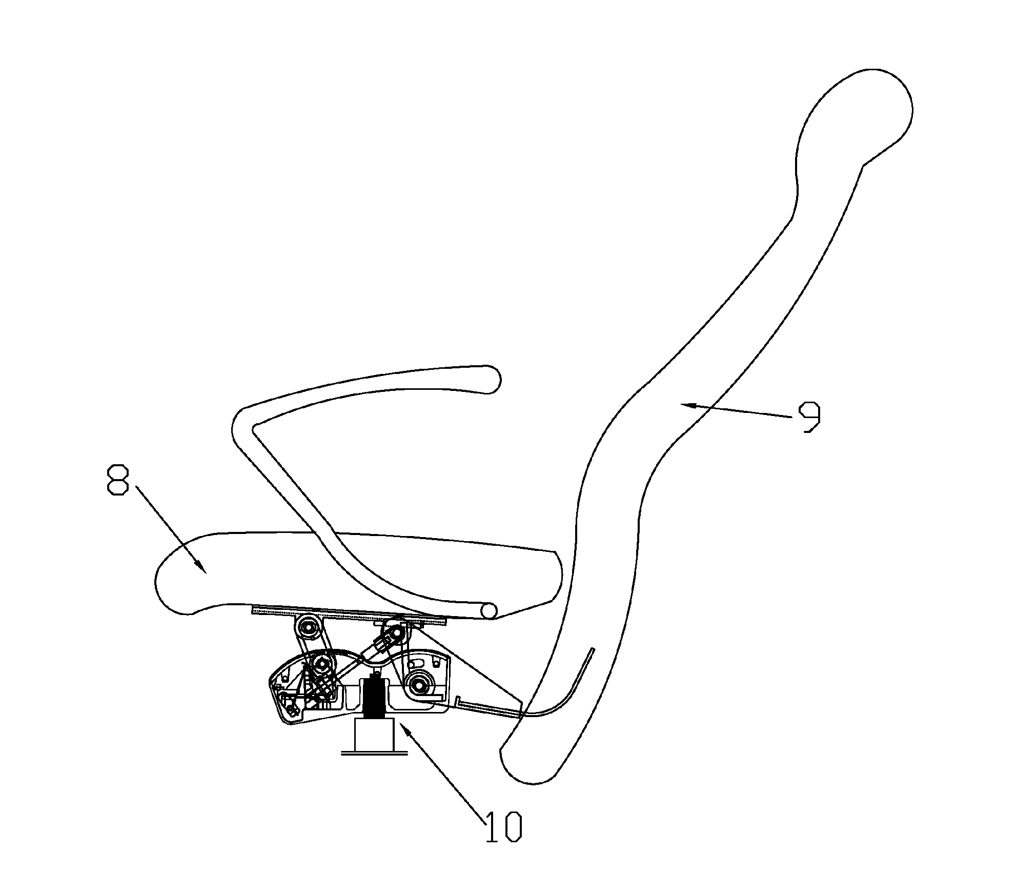
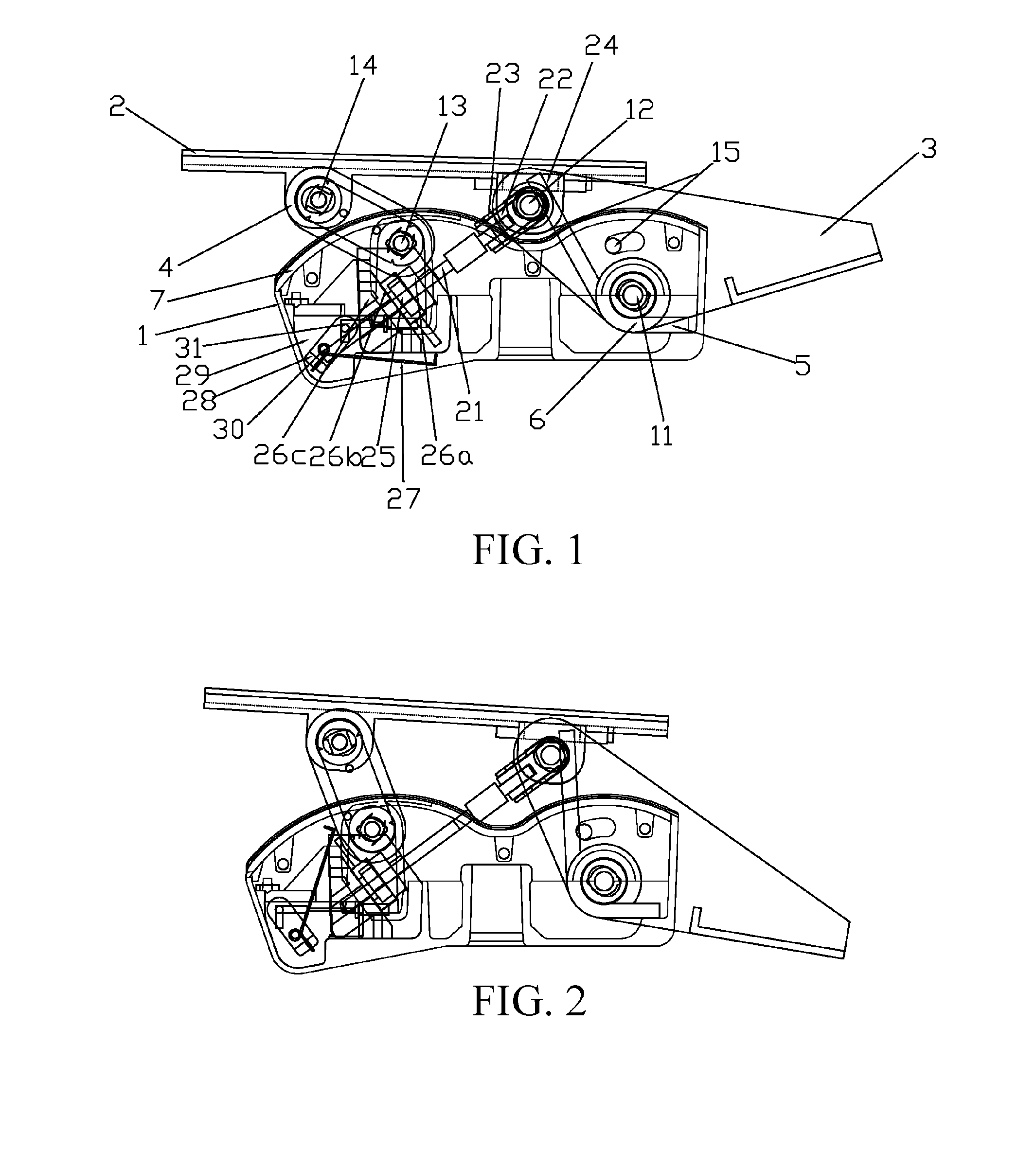
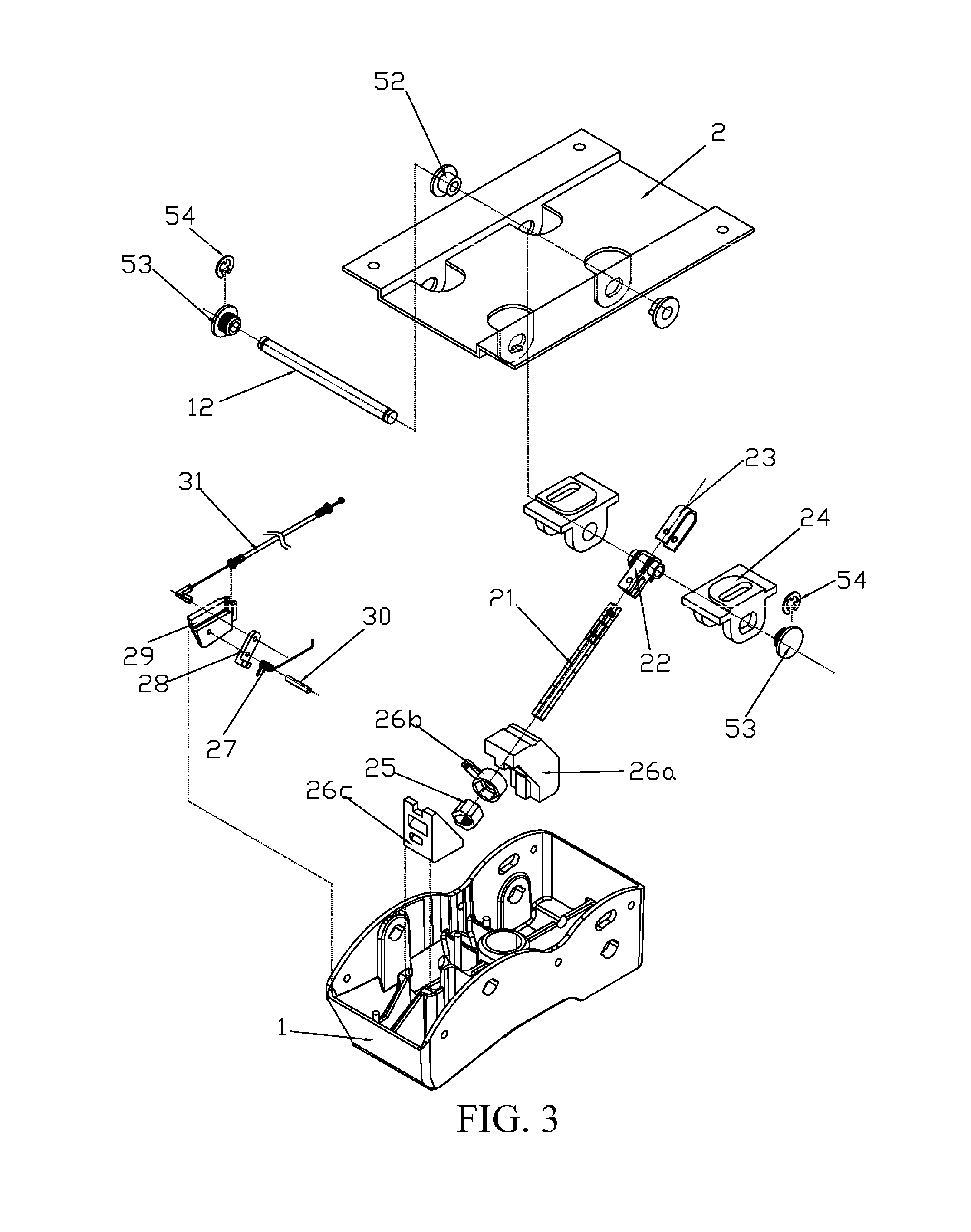
[0050]Referring to FIG. 1 to FIG. 3, according to some embodiments, a chair chassis includes a main tray base 1, a seat bearing plate 2, a movable support member 3 and a pair of movable supporting plates 4, where the seat bearing plate 2 is disposed above the main tray base 1, for bearing a seat 8, a front end of the movable support member 3 is pivotally connected to the seat bearing plate 2 by using a common shaft 12, a lower end of the movable support member 3 is pivotally connected to the main tray base 1 by using a common shaft 11, a lower end of the movable support member 3 is used for connecting a chair backrest 9, the front end, the lower end and the rear end of the movable support member 3 are in a triangle relationship and the front end and the rear end are pivotable by taking the lower end as a fulcrum, the pair of movable supporting plates 4 are located in front of the movable support member 3, upper and lower ends of each movable supporting plate 4 are respectively pivot...


PUM


Abstract

Disclosed is a chair chassis, wherein a seat bearing plate is disposed above a main tray base, for bearing a seat, a front end of a movable support member is pivotally connected to the seat bearing plate, a lower end thereof is pivotally connected to the main tray base, the movable support member is pivotable, a pair of movable supporting plates are located in front of the movable support member, upper and lower ends of each movable supporting plate are respectively pivotally connected to the seat bearing plate and the main tray base, and a pivot where the movable support member and the main tray base are connected is mounted with an elastic member for resisting the movable support member from rotating rearward. A user is subject to appropriate pressure when leaning back against the backrest, and friction between the backrest and the user's back may be reduced.

Description

BACKGROUND OF THE INVENTION[0001]1. Field of Invention[0002]The present application relates to a chair chassis and a chair having the chair chassis.[0003]2. Related Art[0004]For the design of the bearing chassis of the current chair, in order to realize leaning back of the chair backrest, the design is more complex, there are more parts and more screws must be used, which is prone to damage or screw loosening, resulting in a failure. Meanwhile, the design of leaning back makes more use of different modes of springs to bear rearward pressure of the backrest, it is difficult to accurately adapt to a user's weight or activity, rearward movement often may produce excessively light or excessively heavy pressure, and thus more parts are required for calibration purposes. In addition, the distance between the backrest and the seat changes when the backrest is rearward, and the backrest rubs the user's back, resulting in discomfort.SUMMARY OF THE INVENTION[0005]An object of the present appl...

Claims


Application Information

Patent Timeline
Patent Type & Authority Applications(United States)
IPC IPC(8): A47C1/032
CPCA47C1/03222A47C1/03255A47C1/03274A47C1/03272
Inventor HUANG, JUNLI
Owner SHANTOU LISHI FURNITURE
Why Eureka
Try Eureka