Structure and method for fixing lens of optical module

a technology of optical modules and fixing structures, applied in the direction of optics, mountings, instruments, etc., can solve the problems of poor scanning quality and poor image quality, and achieve the effect of substantially improving image quality and balanced torque on the lens

Inactive Publication Date: 2005-11-15
CREATIVE SENSOR INC
View PDF5 Cites 0 Cited by
  • Summary
  • Abstract
  • Description
  • Claims
  • Application Information

AI Technical Summary

Benefits of technology

[0010]It is an aspect of the present invention to provide a lens fixing structure for fixing lens of an optical module in a scanner, a multi-function printer, a fax machine or a copy machine. According to the present invention, the torque on lens is balanced by increasing the height of the slot wall, decreasing the draft angle formed between the second slot wall and the vertical axis and uniforming heights of the fixing gel, so that the quality of image is substantially improved.

Problems solved by technology

If the distance between positions of the rod lens 12 centerline and the light-sensing component 141 centerline is significant, the scanning quality will be bad.
The quality of the obtained image is bad owing to the rod lens effect or photo response non uniformity.

Method used


Image

  • Structure and method for fixing lens of optical module
  • Structure and method for fixing lens of optical module
  • Structure and method for fixing lens of optical module

Examples


Embodiment Construction

[0033]The invention is described more specifically with reference to the following embodiments. It is to be noted that the following descriptions of preferred embodiments of this invention are presented herein for the purpose of illustration and description only; it is not intended to be exhaustive or to be limited to the precise form disclosed.

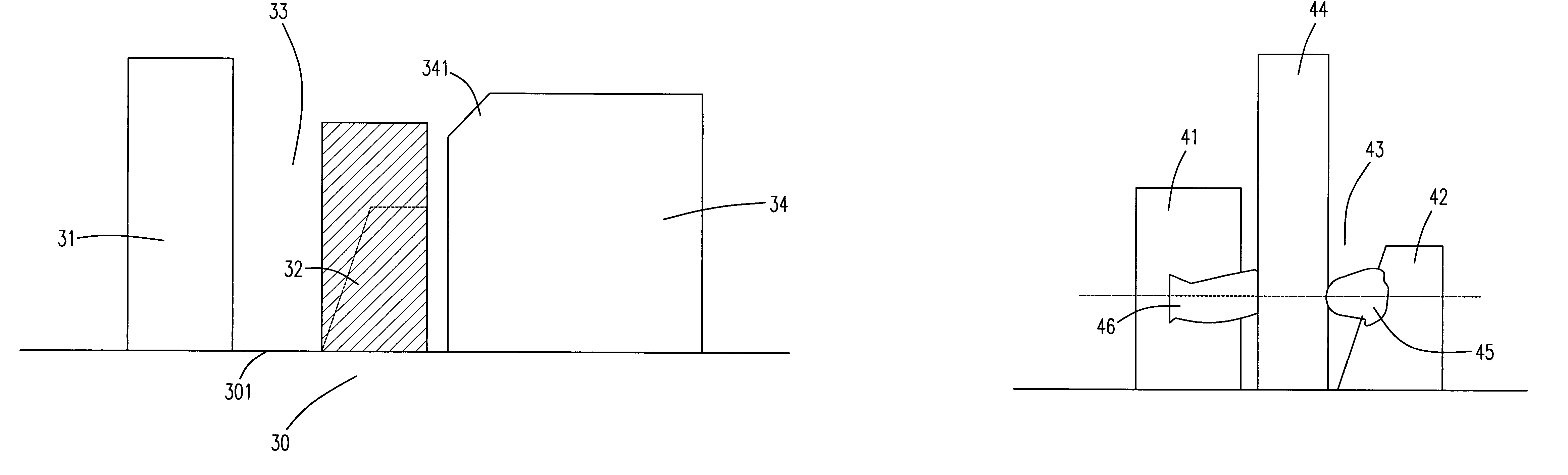
[0034]Please refer to FIG. 3(a) showing a side view of the lens fixing structure according to the preferred embodiment of the present invention. The lens fixing structure is constructed by a first slot wall 31 and a second slot wall 32 of a housing 30, wherein a slot 33 is formed between the first slot wall 31 and the second slot wall 32 for receiving and fixing a lens therein.

[0035]According to the present invention, the height of the slot wall 32 is increased, and subsequently the unbalanced torque is eliminated during loading the fixing gel. The height of the second slot wall 32 is increased by adding a block 321 on the top of the second s...


PUM


Abstract

A lens fixing structure for an optical module of a scanner, a multi-function printer, a fax machine or a copy machine is disclosed. The lens fixing structure for an optical module of a scanner, a multi-function printer, a fax machine or a copy machine, wherein the optical module has a housing, and the lens fixing structure is installed on the housing, includes a slot structure for placing and fixing a lens therein, wherein the slot structure includes a first slot wall positioned on the housing; and a second slot wall positioned on the housing and being parallel to the first slot wall, wherein the second slot wall is perpendicular to a surface of the housing.

Description

FIELD OF THE INVENTION[0001]This invention relates to a lens fixing structure and a method for fixing lens of an optical module in a scanner, a multi-function printer, a fax machine or a copy machine, and more particularly to a lens fixing structure and a method for fixing lens of a scanner, a multi-function printer, a fax machine or a copy machine having a contact image sensor.BACKGROUND OF THE INVENTION[0002]In operation of a scanner, light is emitted from a source to a object, then is reflected by a set of lens. Then, the light is focused on and received by a charge-couple device (CCD) or a complementary metal oxide semiconductor (CMOS). The light signal is transferred into electric signal by such light-sensing component, so that data of analog or digital pixels are produced. During the scanning, the intensity of the light reflected from different areas of the scanned object is detected by the CCD. The low density of light is reflected from a darker area of the scanned object and...

Claims


Application Information

Patent Timeline
Patent Type & Authority Patents(United States)
IPC IPC(8): G02B7/02
CPCG02B7/02
Inventor TA, SU LINGFANG, LIN MING
Owner CREATIVE SENSOR INC
Why Eureka
Try Eureka