Electrical connector assembly with pick up device

a technology of electrical connectors and pick-up devices, which is applied in the direction of electrical apparatus, line/current collector details, and coupling device connections, etc., can solve the problems of electrical connection failure between the electrical connector unit b>801/b> and the printed circuit board, and achieve the effect of counterbalance force torqu

Inactive Publication Date: 2008-12-23
HON HAI PRECISION IND CO LTD
View PDF7 Cites 0 Cited by
  • Summary
  • Abstract
  • Description
  • Claims
  • Application Information

AI Technical Summary

Benefits of technology

[0005]An electrical connector assembly according to an embodiment of the present invention includes an electrical connector unit to be mounted onto a printed circuit board, a supporting member for supporting the electrical connector unit, and a pick up device attachable onto the electrical connector unit. The supporting member includes a supporting portion extending from one side of the electrical connector unit, with the supporting portion defining a supporting surface resting on the printed circuit board. The pick up device includes a balance section extending from another side of the electrical connector unit. The balance section defines a balance surface extending parallel to the supporting surface such that when the pick up device is attached onto the printed circuit board, the balance surface of the pick up device is operable to be rested on the printed circuit board so as to counterbalance force torque caused by introduce of the supporting portion. Thus, no electrical connection failure will be generated between the electrical connector unit and the printed circuit board.

Problems solved by technology

This will result in the electrical connection failure between the electrical connector unit 801 and the printed circuit board 81 due to the deflectable terminals.

Method used


Image

  • Electrical connector assembly with pick up device
  • Electrical connector assembly with pick up device
  • Electrical connector assembly with pick up device

Examples


Embodiment Construction

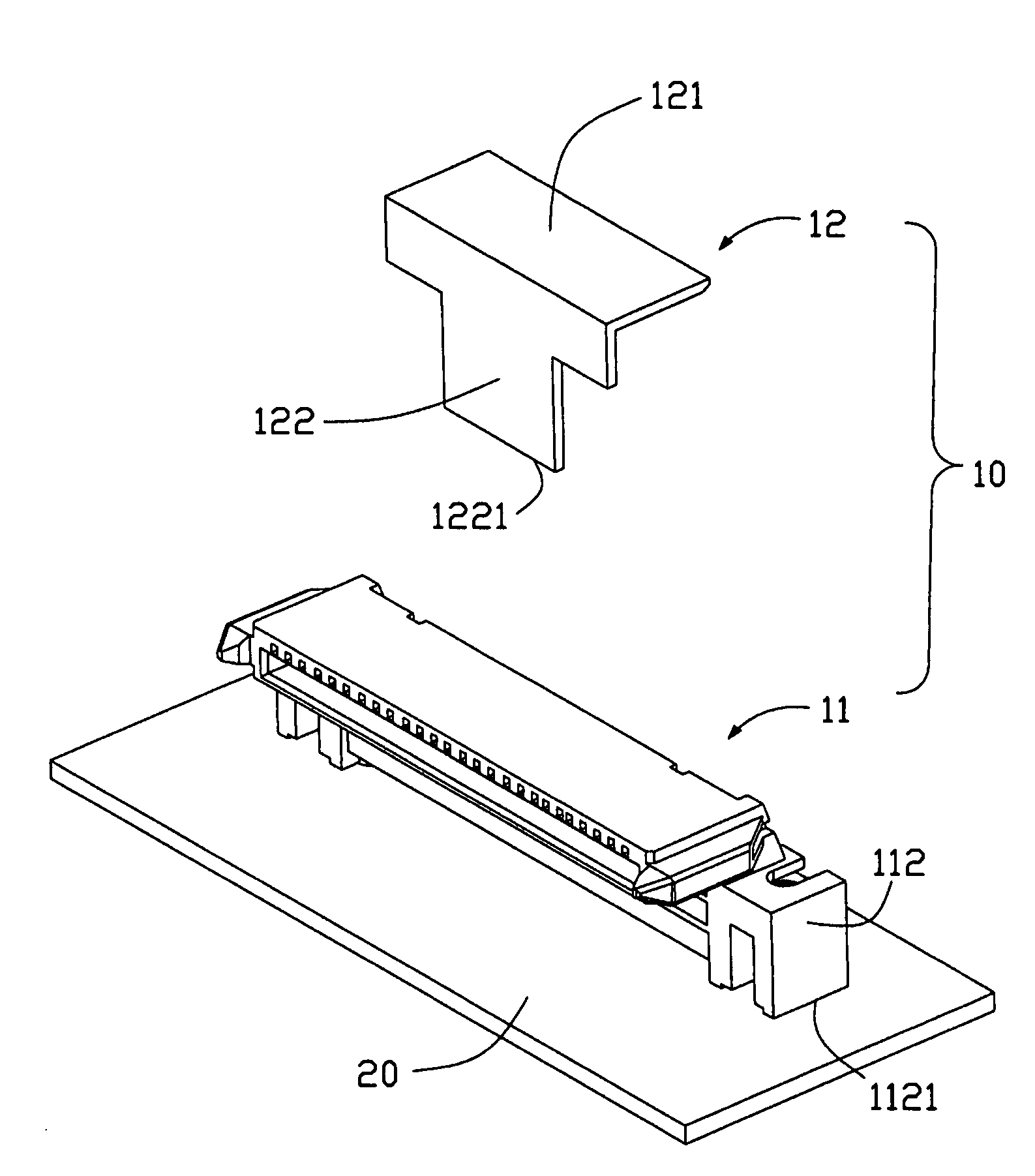
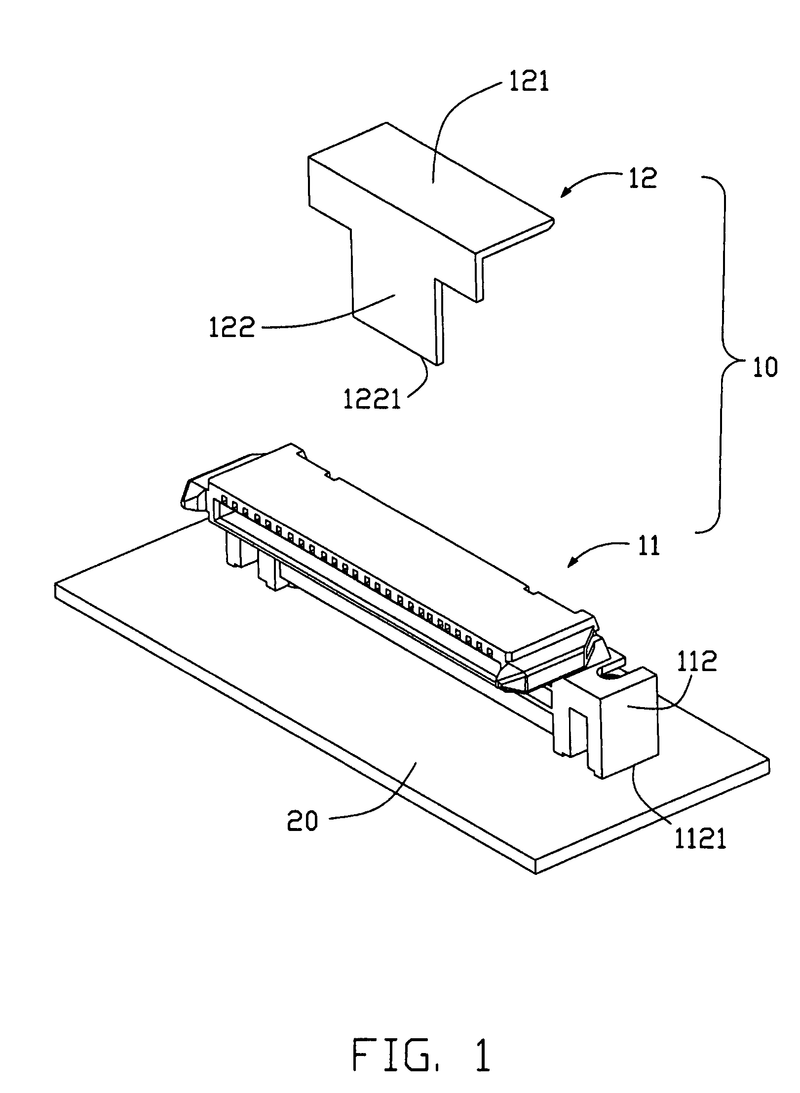
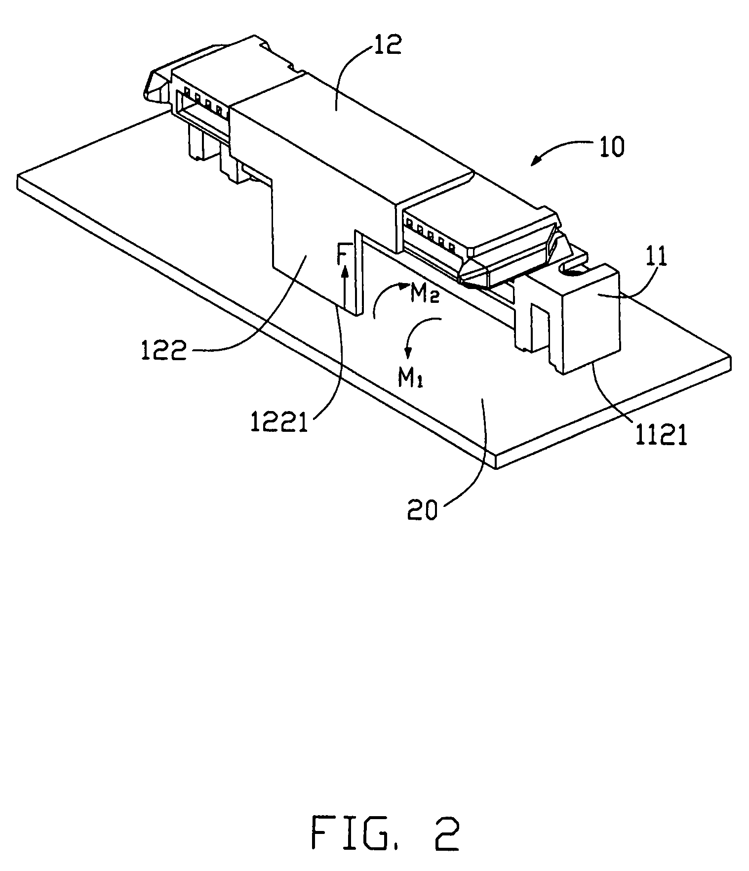
[0010]Referring to FIGS. 1 and 2, an electrical connector assembly 10 is shown to include an electrical connector unit 11 to be mounted onto a printed circuit board 20, a supporting member 112 for supporting the electrical connector unit 11, and a pick up device 12 attached onto the electrical connector unit 11. The electrical connector unit 11 is defined as at least a part of an electrical connector, where a multiply of terminals (not shown) are embedded.

[0011]The supporting member includes a first supporting portion sandwiched between the electrical connector unit 11 and the printed circuit board 20, and a second supporting portion 112 arranged extending from one side of the electrical connector unit 11. The second supporting portion 112 defines a supporting surface 1121 resting on the printed circuit board 20. The electrical connector unit 11 is laterally offset with respect to the second supporting portion 112 in a transverse direction perpendicular to a length direction of the ...


PUM


Abstract

An electrical connector assembly includes an electrical connector unit (11) to be mounted onto a printed circuit board (11), a supporting member for supporting the electrical connector unit, and a pick up device (12) attachable onto the electrical connector unit. The supporting member includes a supporting portion (112) extending from one side of the electrical connector unit, with the supporting portion defining a supporting surface (1121) resting on the printed circuit board. The pick up device includes a balance section (122) defining a balance surface (1221) extending parallel to the supporting surface such that when the pick up device is attached onto the printed circuit board, the balance surface of the pick up device is operable to be rested on the printed circuit board so as to counterbalance force torque caused by introduce of the supporting portion.

Description

BACKGROUND OF THE INVENTION[0001]1. Field of the Invention[0002]The present invention relates to the art of electrical connectors, and more particularly to an electrical connector assembly including a pick up device attached thereto.[0003]2. Description of the Related Art[0004]One conventional electrical connector assembly is shown in FIG. 3 to include an electrical connector unit 801 mounted onto a printed circuit board 81, and a supporting member for supporting the electrical connector unit 801. The supporting member includes a first supporting portion sandwiched between the electrical connector unit 801 and the printed circuit board 81, and a second supporting portion 802 arranged extending from one side of the electrical connector unit 801, with the second supporting portion 802 defining a supporting surface 8020 resting on the printed circuit board 81. Due to having the second supporting portion 802 at one side of the electrical connector unit 801, gravity center of the electri...

Claims


Application Information

Patent Timeline
Patent Type & Authority Patents(United States)
IPC IPC(8): H01R13/44
CPCH01R43/205H01R12/716Y10S439/94
Inventor YUAN, WEIHSIAO, YU-SAN
Owner HON HAI PRECISION IND CO LTD
Why Eureka
Try Eureka