
Multifunctional anemograph

An anemometer and multi-functional technology, applied in the field of multi-functional anemometers, can solve the problems of easy to be buried, high rotational vibration of rotating parts, unbalanced torque of rotating parts, etc., so as to improve measurement accuracy, reduce dependence, and improve height Effect

Inactive Publication Date: 2020-12-01
江苏鸿渐投资咨询管理有限公司
View PDF14 Cites 0 Cited by
  • Summary
  • Abstract
  • Description
  • Claims
  • Application Information

AI Technical Summary

Problems solved by technology

[0004] The purpose of the present invention is to provide a multifunctional anemometer to solve the problem that the existing anemometer proposed in the above background technology is not equipped with a heat preservation and heating device, and its internal components cannot operate effectively in a low temperature environment, making it difficult for the anemometer to adapt In the polar environment, and the support of the existing anemometer is fixed, and in the polar environment, affected by the wind and snow, the height of the ice surface in some areas gradually rises, the existing anemometer cannot raise the height, it is easy to be buried, and the The mobile anemometer is only provided with one-way support, which makes the moment of the rotating part unbalanced, which may easily cause vibration when the rotating part rotates at a high degree, and then affects the monitoring accuracy of the anemometer

Method used


Image

  • Multifunctional anemograph
  • Multifunctional anemograph
  • Multifunctional anemograph

Examples


Embodiment Construction

[0030] The following will clearly and completely describe the technical solutions in the embodiments of the present invention with reference to the accompanying drawings in the embodiments of the present invention. Obviously, the described embodiments are only some, not all, embodiments of the present invention. Based on the embodiments of the present invention, all other embodiments obtained by persons of ordinary skill in the art without making creative efforts belong to the protection scope of the present invention.

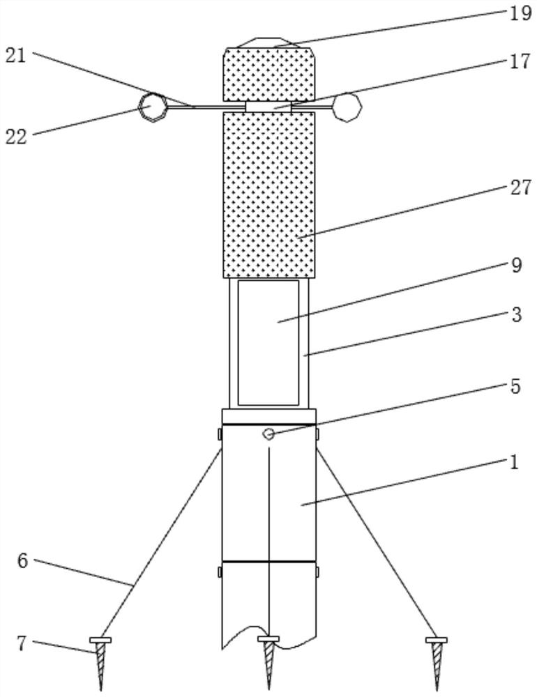
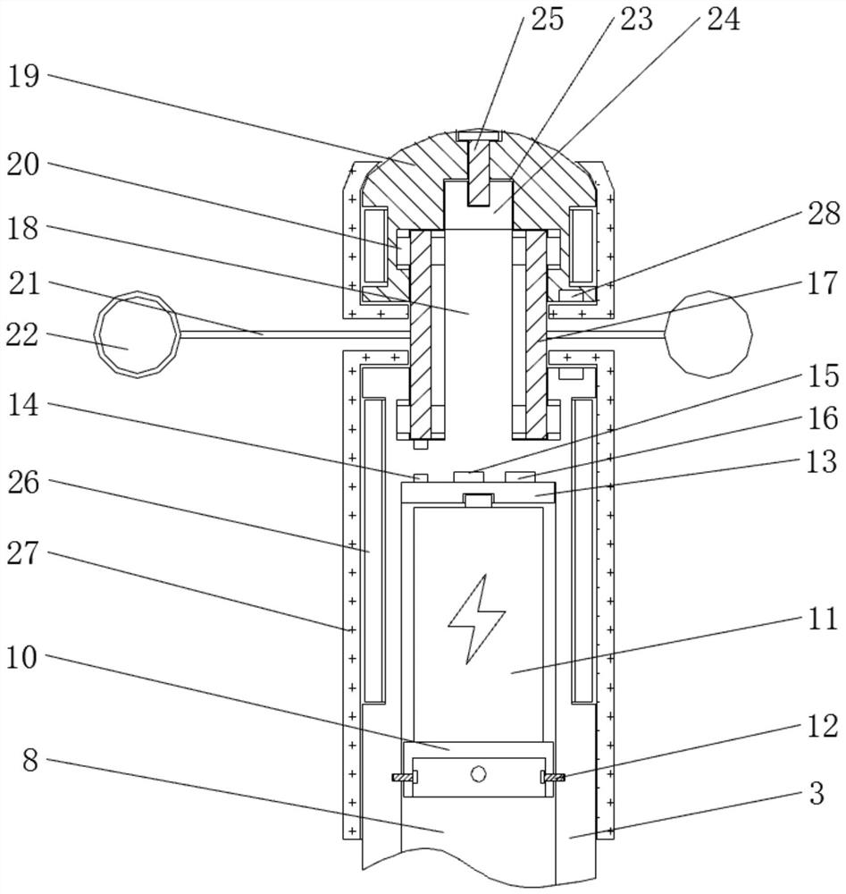
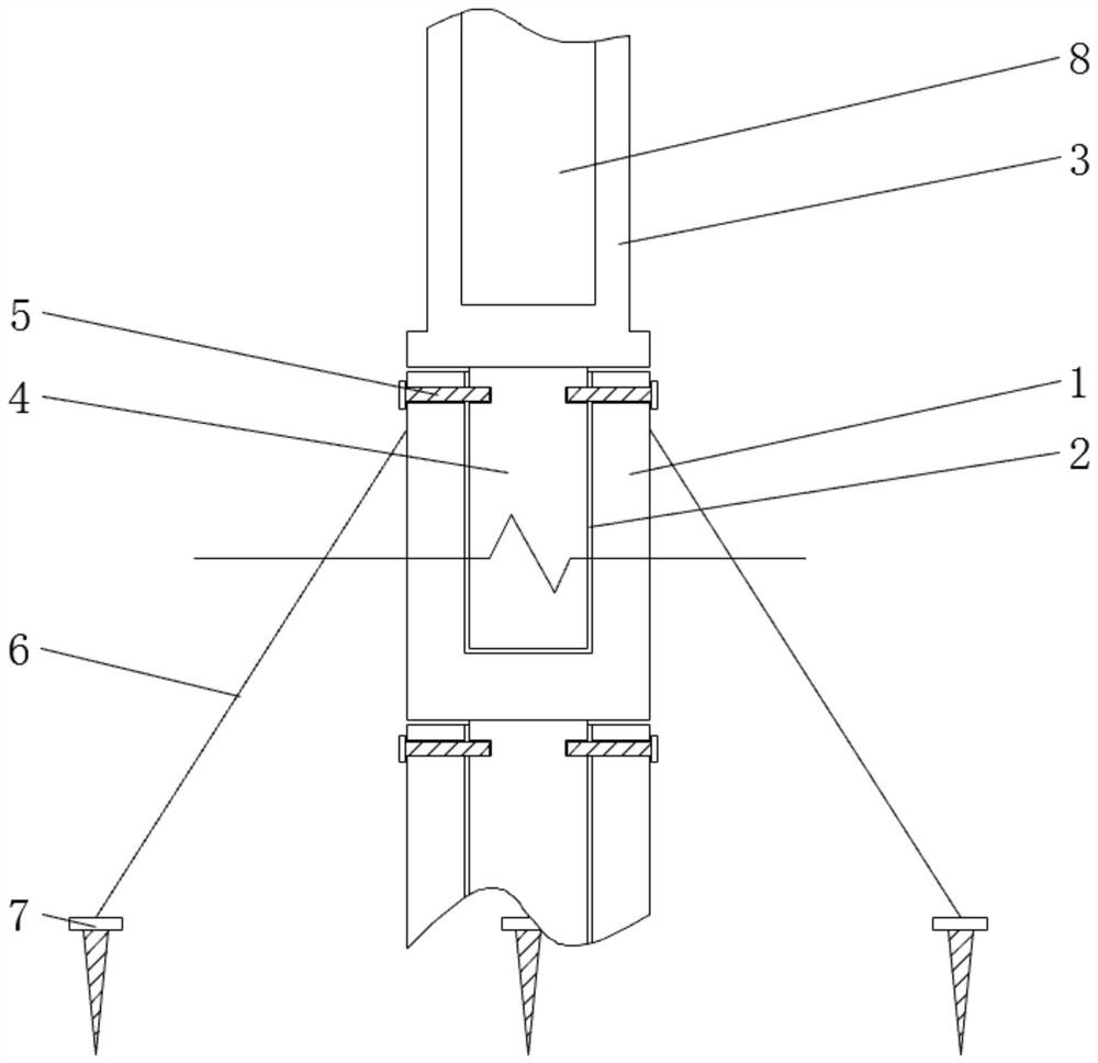
[0031] see Figure 1-6 , the present invention provides a technical solution: a multifunctional anemometer, such as figure 1 and image 3 As shown, the top of the connecting sleeve 1 is provided with a connecting hole 2, and a fixed casing 3 is arranged above the uppermost connecting sleeve 1, and a resistance heater 26 is installed on the outer surface of the fixed casing 3 and the outer surface of the movable casing 19, and is set The thermal insulation la...


PUM


Abstract

The invention discloses a multifunctional anemograph which comprises connecting sleeves, first bolts, a battery jar, a second bolt, a rotating piece, a limiting hole and a third bolt, a connecting hole is formed in the top of each connecting sleeve; and a fixed case is arranged above the connecting sleeve on the uppermost side, connecting columns are fixed to the bottom of the fixed case and the bottoms of the connecting sleeves, the fixed case and the connecting sleeve on the uppermost side are connected through the connecting columns, every two adjacent connecting sleeves are connected through the connecting columns, and the first bolts penetrate through the connecting sleeves to be in threaded connection with the connecting columns. The multifunctional anemograph is provided with a movable case and a center shaft; a rotating piece is rotationally connected with the outer side of the center shaft through a ball bearing; meanwhile, the rotating piece is rotationally connected with thefixed case and the movable case through other ball bearings, so that the upper side and the lower side of the rotating piece are supported at the same time, the moment of force of the rotating pieceis kept balanced, vibration of the rotating piece during high-speed rotation is reduced, and the measurement accuracy of the anemograph is improved.

Description

technical field [0001] The invention relates to the technical field of anemometers, in particular to a multifunctional anemometer. Background technique [0002] The anemometer is an instrument for measuring the surrounding wind speed. It is mainly used for regional meteorological monitoring. Among them, the wind cup anemometer has the advantages of wide measurement range and long service life, so it is widely used. [0003] Existing anemometers are not equipped with thermal insulation and heating devices, and their internal components cannot operate effectively in low-temperature environments, making it difficult for the anemometer to adapt to the polar environment, and the brackets of the existing anemometers are fixed. In the polar environment, Affected by the wind and snow, the height of the ice surface in some areas gradually rises. The existing anemometer cannot raise the height and is easily buried, and the moving anemometer is only provided with one-way support, which...

Claims


Application Information

Patent Timeline
IPC IPC(8): G01P5/07
CPCG01P5/07
Inventor 唐力张晓红张徐莹杨富珍王薇徐梦晨谈雪平刘长俊李雁鹏张佳华吕佳夏
Owner 江苏鸿渐投资咨询管理有限公司
Learn More