Connection apparatus

Inactive Publication Date: 2015-10-01
MAGMA GLOBAL
View PDF17 Cites 30 Cited by
  • Summary
  • Abstract
  • Description
  • Claims
  • Application Information

AI Technical Summary

Benefits of technology

[0010]The present applicant has invented an apparatus which deals with issues relating to existing pipe spools known in the art. Accordingly, the present applicant has invented a deformable pipe assemb

Problems solved by technology

During installation and while in use, the pipe spool may be subjected to external occurrences, for example, thermal distortion, environmental loading or pressure loading.
Pipe spools therefore require significant preparation before installation and are expensive to design, fabricate, install and operate due to the associated weight and proportions.
It will be appreciated that this may result in delays in the installation of subsea systems and results in very strict manufacturing tolerances.
Pipe spools may also be manufactured using non bon

Method used


Image

  • Connection apparatus
  • Connection apparatus
  • Connection apparatus

Examples


Example

DETAILED DESCRIPTION OF THE DRAWINGS

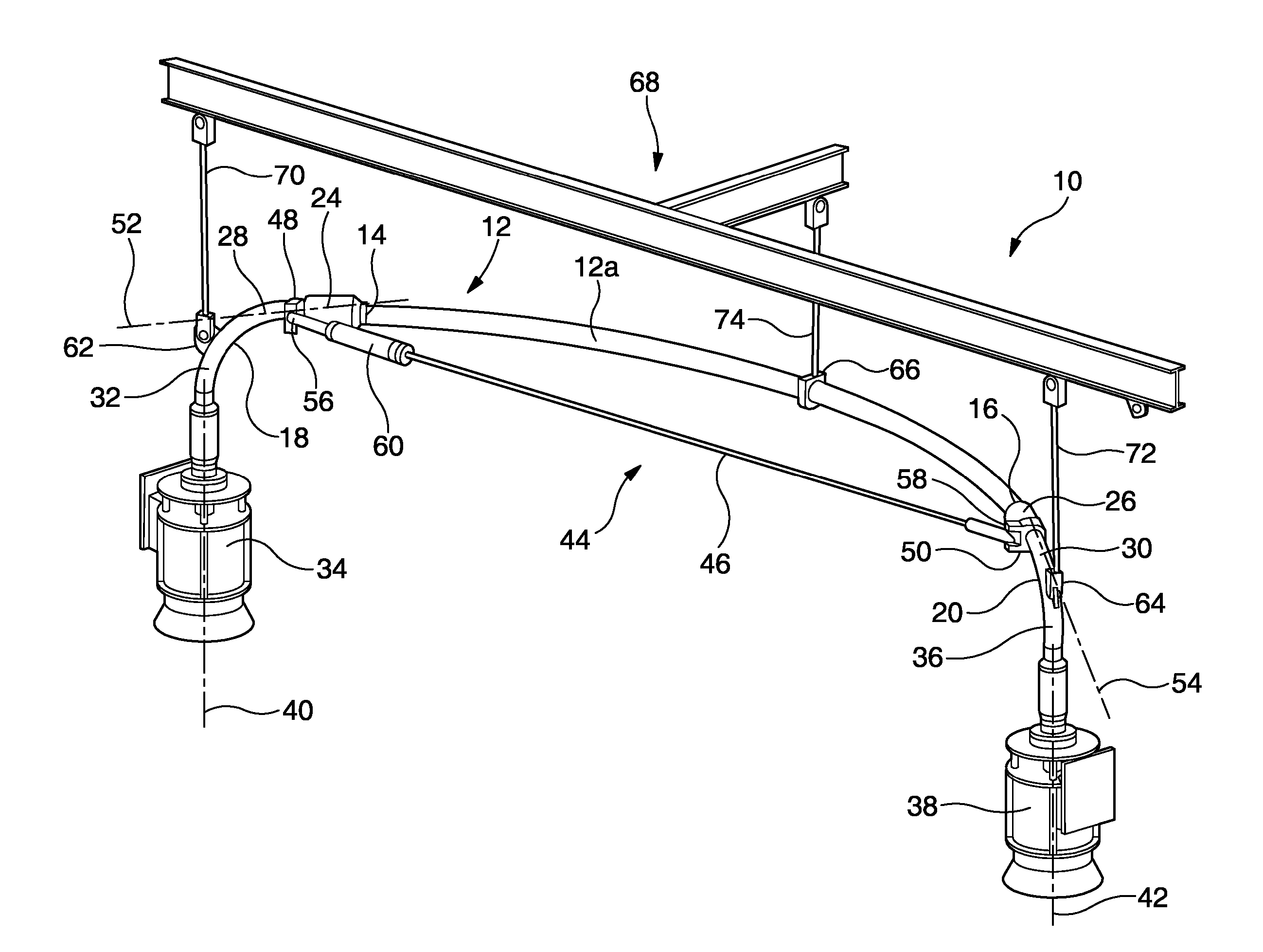
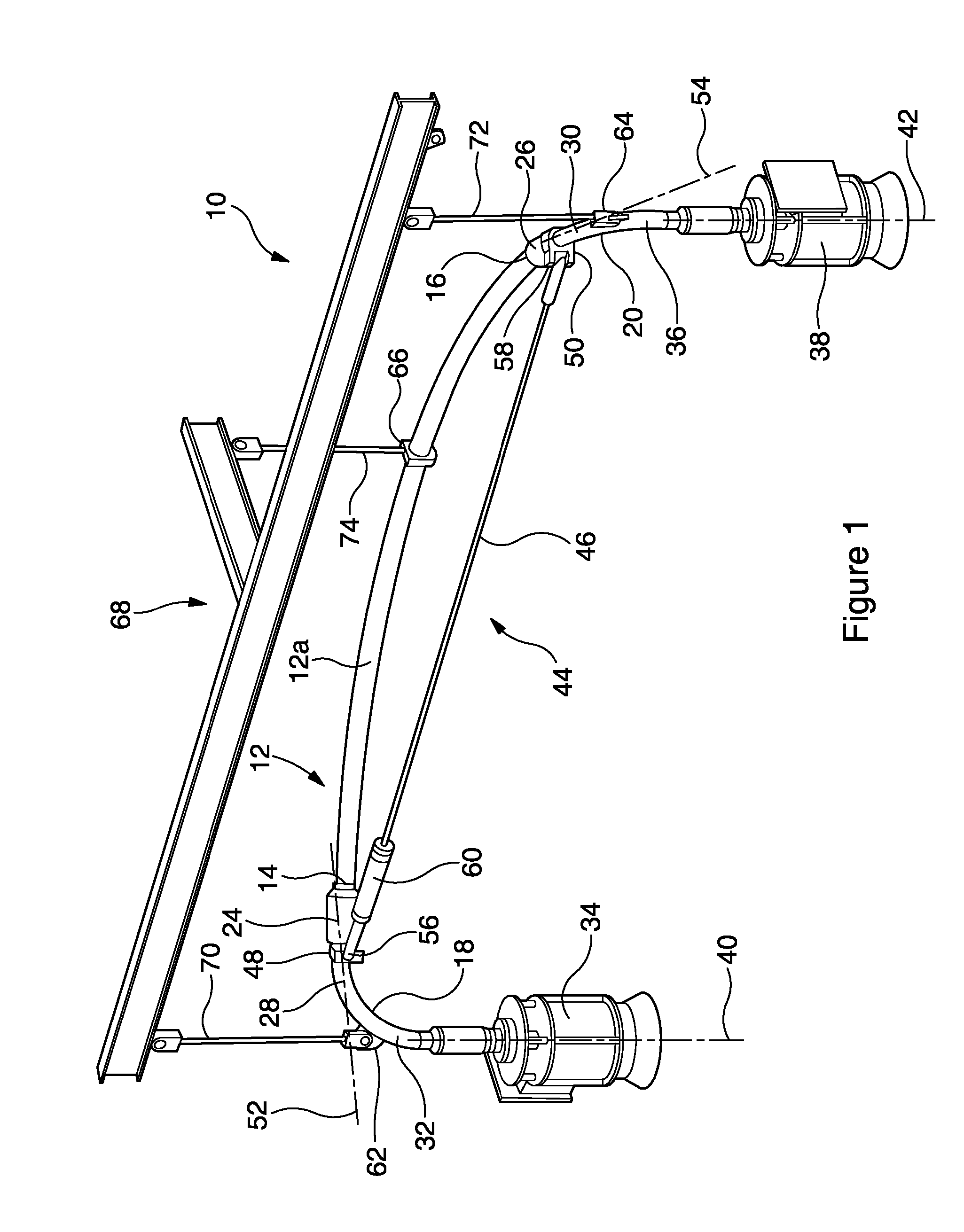
[0099]A connection apparatus 10 is shown in FIG. 1. The connection apparatus comprises a deformable pipe assembly 12 that comprises a flexible portion 12a. Opposing ends 14, 16 of the flexible portion 12a are provided with first and second rigid portions 18, 20. The rigid portions 18 and 20 each comprise a bend wherein, in this embodiment, each of the bends are substantially at 90 degrees. However, it will be appreciated that the rigid portions 18 and 20 may comprise a bend at any angle, as required. First and second connectors 34, 38 are provided on the distil ends of the first and second rigid portions 18, 20 respectively. In this way, the deformable pipe assembly 12 defines a communication path from the first and second connectors 34, 38.

[0100]The connection apparatus further comprises an adjusting assembly 60 for applying a force on the flexible portion 12a. The adjusting assembly 60 is coupled between the first and second rigid portions at an...


PUM

PropertyMeasurementUnit
Thicknessaaaaaaaaaa
Forceaaaaaaaaaa
Lengthaaaaaaaaaa

Abstract

An apparatus (10) for providing fluid communication between first and second connection points (34,38) comprises a deformable pipe assembly (12) including a composite material. A first connector (34) is mounted at one end of the deformable pipe assembly and is configured for connection with a first connection point and a second connector (38) is mounted at an opposite end of the deformable pipe assembly and is configured for connection with a second connection point. An adjusting assembly (44) is configured to apply a force between separated regions of the deformable pipe assembly, such that deformation of the deformable pipeline assembly is responsive to the adjusting assembly to permit a relative separation of the first and second connectors to be adjusted.

Description

FIELD OF THE INVENTION[0001]The present invention relates to an apparatus for use in providing fluid communication between first and second connection points, such as those provided in two piping systems.BACKGROUND OF THE INVENTION[0002]The subsea oil and gas industry uses subsea Xmas trees, manifolds, flowlines and pipelines to produce and export hydrocarbons. These subsystems are connected by piping spools that provide pressure tight communication from one package to another.[0003]Typically, pipe spools are pre-designed with a specified geometry and length, which may be typically in the range 1 to 100 m. Each opposing end of a pipe spool is connected to a corresponding subsea equipment package using an interface hub or flange.[0004]Pipe spools require exacting specifications in order to allow installation and perform correctly during their service life. The piping spool typically consists of a length of pipe, incorporating a number of 90 degree bends with a flange or other mechani...

Claims


Application Information

Patent Timeline
IPC IPC(8): E21B43/013F16L27/12F16L43/02
CPCE21B43/013F16L27/12F16L43/02Y10T29/49826
Inventor HATTON, STEPHEN
Owner MAGMA GLOBAL
Why Eureka
Try Eureka