Diffraction element, objective lens unit, optical pickup, optical disc apparatus and design method for diffraction element

Inactive Publication Date: 2007-11-08
SONY CORP
View PDF2 Cites 2 Cited by
  • Summary
  • Abstract
  • Description
  • Claims
  • Application Information

AI Technical Summary

Benefits of technology

[0027] According to one aspect of the present invention, it is easily determined that, when the refraction indexes n1 and n2 of the first and second materials for each wavelength λ satisfy the condition (1), the diffraction element diffracts the third wavelength λ3 without diffracting the first and second wavelengths λ1 and λ2. It is also determined that, when the condition (2) is satisfied, the diffraction element diffracts the second and third wavelengths λ2 and λ3 without diffracting the first wavelength λ1. This allows easy selection of materials suitable for the diffraction element. Thus, the design method allows easy design of the diffraction element with good characteristics.
[0028] According to another aspect of the present invention, when the refraction indexes n1 and n2 of the first and second materials for each wavelength λ satisfy the condition (1) the diffraction element diffracts the third wavelength λ3 without diffracting the first and second wavelengths λ1 and λ2. On the other hand, when the condition (2) is satisfied the diffraction element diffracts the second and third wavelengths λ2 and λ3 without diffracting the first wavelength λ1. Thus, the diffraction element presents good characteristics.
[0029] According to another aspect of the present invention, when the refraction indexes n1 and n2 of the first and second materials for each wavelength λ satisfy the condition (1) the diffraction element diffracts the third wavelength λ3 without diffracting the first and second wavelengths λ1 and λ2. On the other hand, when the condition (2) is satisfied the diffraction el

Problems solved by technology

However, the criteria for selecting materials are not clearly defined to have good characteristics and to improve the diffraction and transmission efficiencies of optical beams

Method used


Image

  • Diffraction element, objective lens unit, optical pickup, optical disc apparatus and design method for diffraction element
  • Diffraction element, objective lens unit, optical pickup, optical disc apparatus and design method for diffraction element
  • Diffraction element, objective lens unit, optical pickup, optical disc apparatus and design method for diffraction element

Examples


Example

[0045] An embodiment of the present invention will be described in detail with reference to the accompanying drawings.

(1) Configuration of Optical Disc Device

(1-1) Overall Configuration of Optical Disc Device

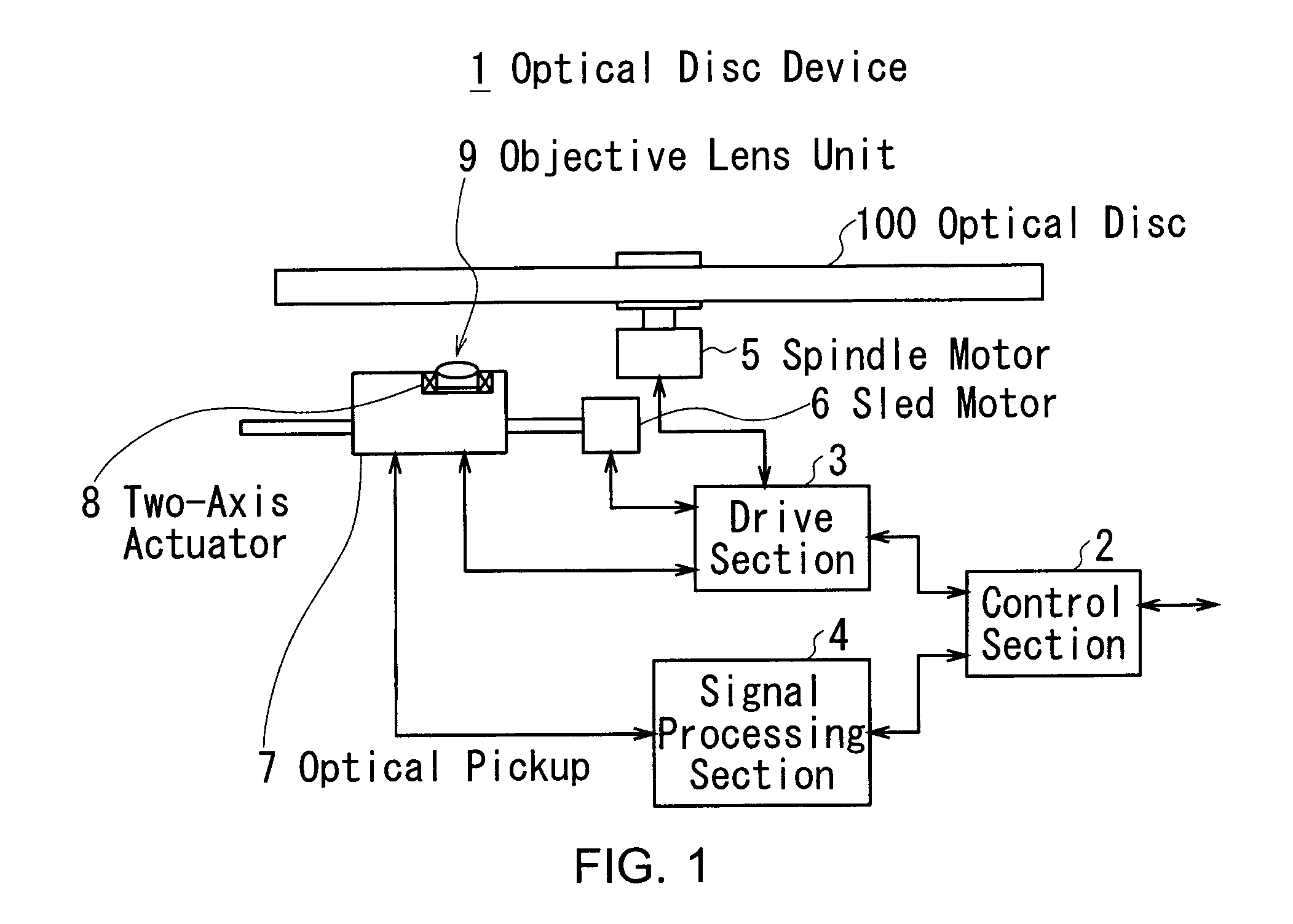
[0046]FIG. 1 shows an optical disc device 1 that supports an optical disc 100 of CD, DVD and BD. The optical disc device 1 reproduces signals from the optical disc 100.

[0047] A control section 2 takes overall control of the optical disc device 1. After the optical disc 100 is inserted into the optical disc device 1, the control section 2 controls, in response to a playback command or the like from external devices (not shown), a drive section 3 and a signal processing section 4 to reproduce information from the optical disc 100.

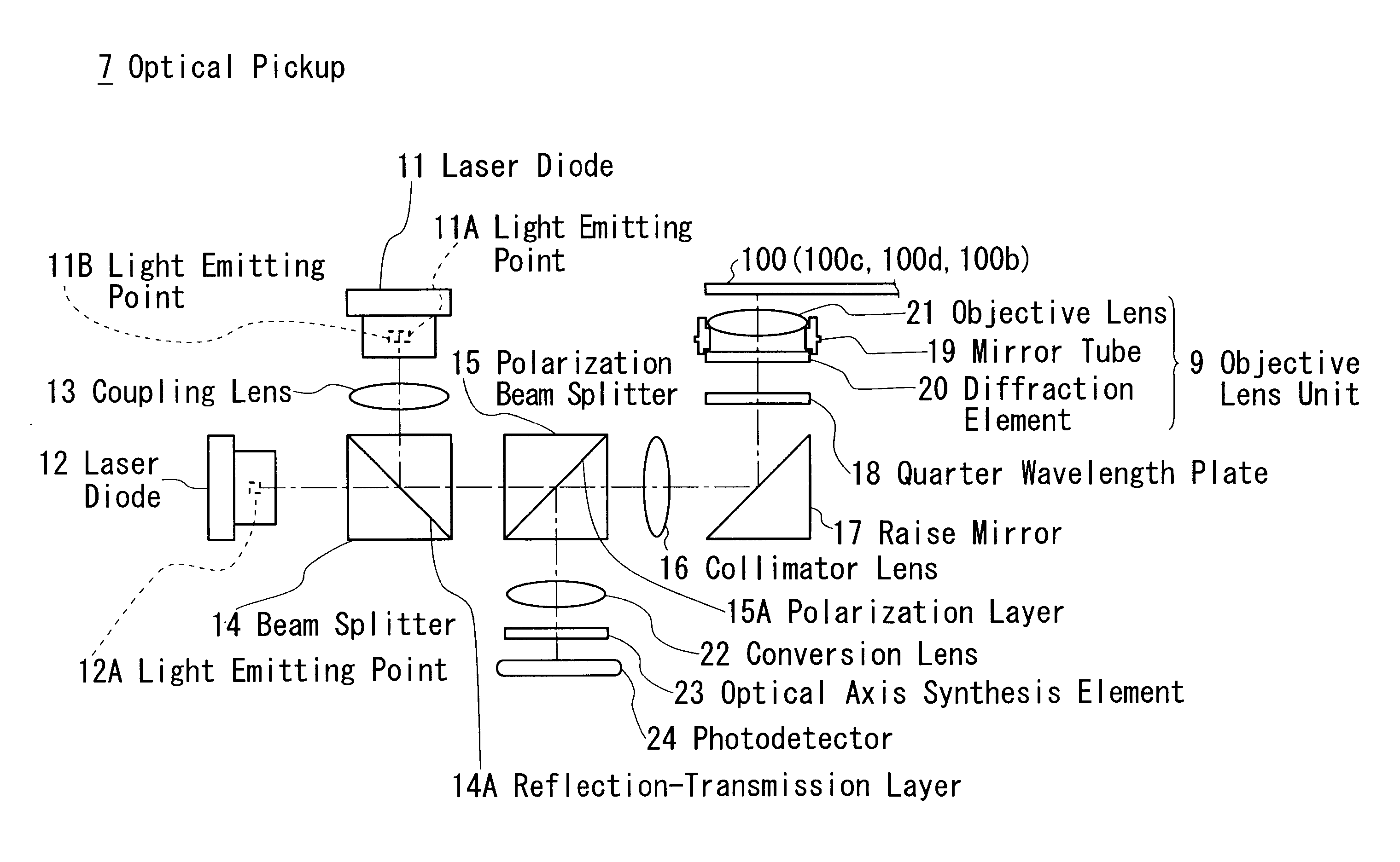
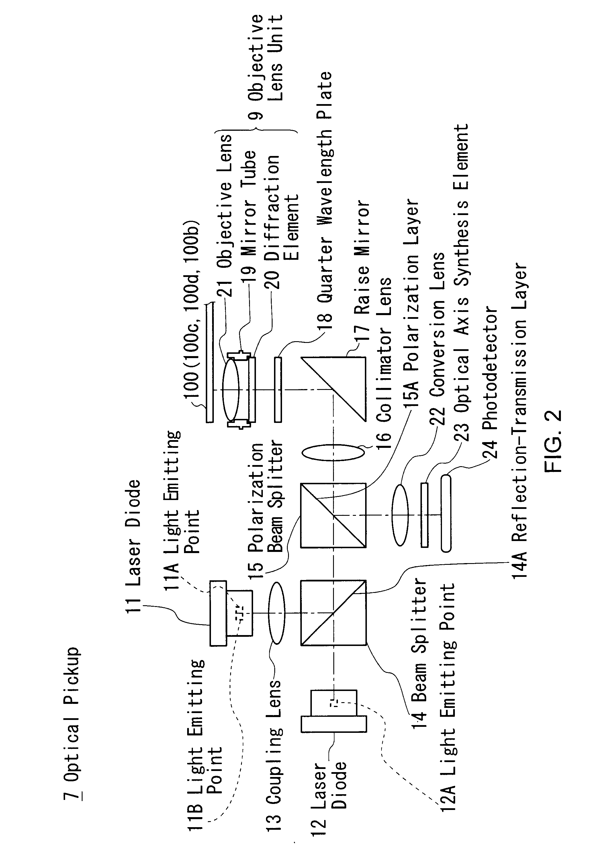
[0048] The signal processing section 4 is controlled by the control section 2. The signal processing section 4 controls an optical pickup 7 to emit an optical beam to the optical disc 100 from an objective lens unit 9.

[0049] The drive section 3 und...


PUM


Abstract

The first and second materials of the diffraction element are selected such that the first material's refraction indexes n11), n12) and n13) for the first, second and third wavelengths λ1, λ2 and λ3 and the second material's refraction indexes n21), n22) and n23) for the first, second and third wavelengths λ1, λ2 and λ3 satisfy one of the conditions (1) or (2).

Description

CROSS REFERENCES TO RELATED APPLICATIONS [0001] The present invention contains subject matter related to Japanese Patent Application JP2006-098707 filed in the Japanese Patent Office on Mar. 31, 2006, the entire contents of which being incorporated herein by reference. BACKGROUND OF THE INVENTION [0002] 1. Field of the Invention [0003] The present invention relates to a diffraction element, objective lens unit, optical pickup, optical disc apparatus and design method for a diffraction element, and is preferably applied to an optical disc device, for example. [0004] 2. Description of Related Art [0005] In recent years, there is an optical disc device that supports a plurality of types of optical discs: “Blu-ray Disc (Registered Trademark)” (BD) along with well-known formats such as Compact Disc (CD) and Digital Versatile Disc (DVD). [0006] The optical disc device chooses one of the following types of optical beam in accordance with the format of an optical disc inserted: approximatel...

Claims


Application Information

Patent Timeline
IPC IPC(8): G11B7/00
CPCG02B5/1866G11B7/1275G11B2007/0006G11B7/1374G11B7/1353
Inventor YAMADA, TAKATOSHIKAWAKITA, SATOSHISATO, JINKANNO, KYUAIBA, MOTOO
Owner SONY CORP
Why Eureka
Try Eureka