
FPC design and HGA assembly process

Inactive Publication Date: 2005-06-02
SHANG PING
View PDF11 Cites 3 Cited by
  • Summary
  • Abstract
  • Description
  • Claims
  • Application Information

AI Technical Summary

Benefits of technology

[0032] Since the process of the present invention is performed by changing slider bounding from the suspension level to the FPC level, the problem of damage of a suspension by clamps and that of suspension pitch / roll change by heating are eliminated automatically.
[0033] It is very easy for an SBB process to design a fixture and machine to manufacture such a kind of slider bounding on an FPC and easy for mass production, with no damage to the suspension.

Problems solved by technology

However, it is very difficult for the conventional assembly process to manufacture this reverse type of HGA.

Method used


Image

  • FPC design and HGA assembly process
  • FPC design and HGA assembly process
  • FPC design and HGA assembly process

Examples


Embodiment Construction

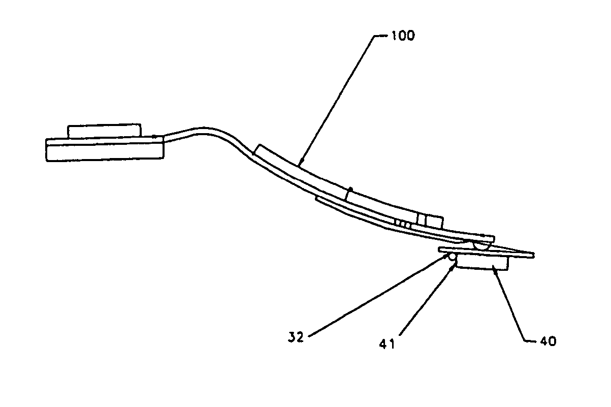
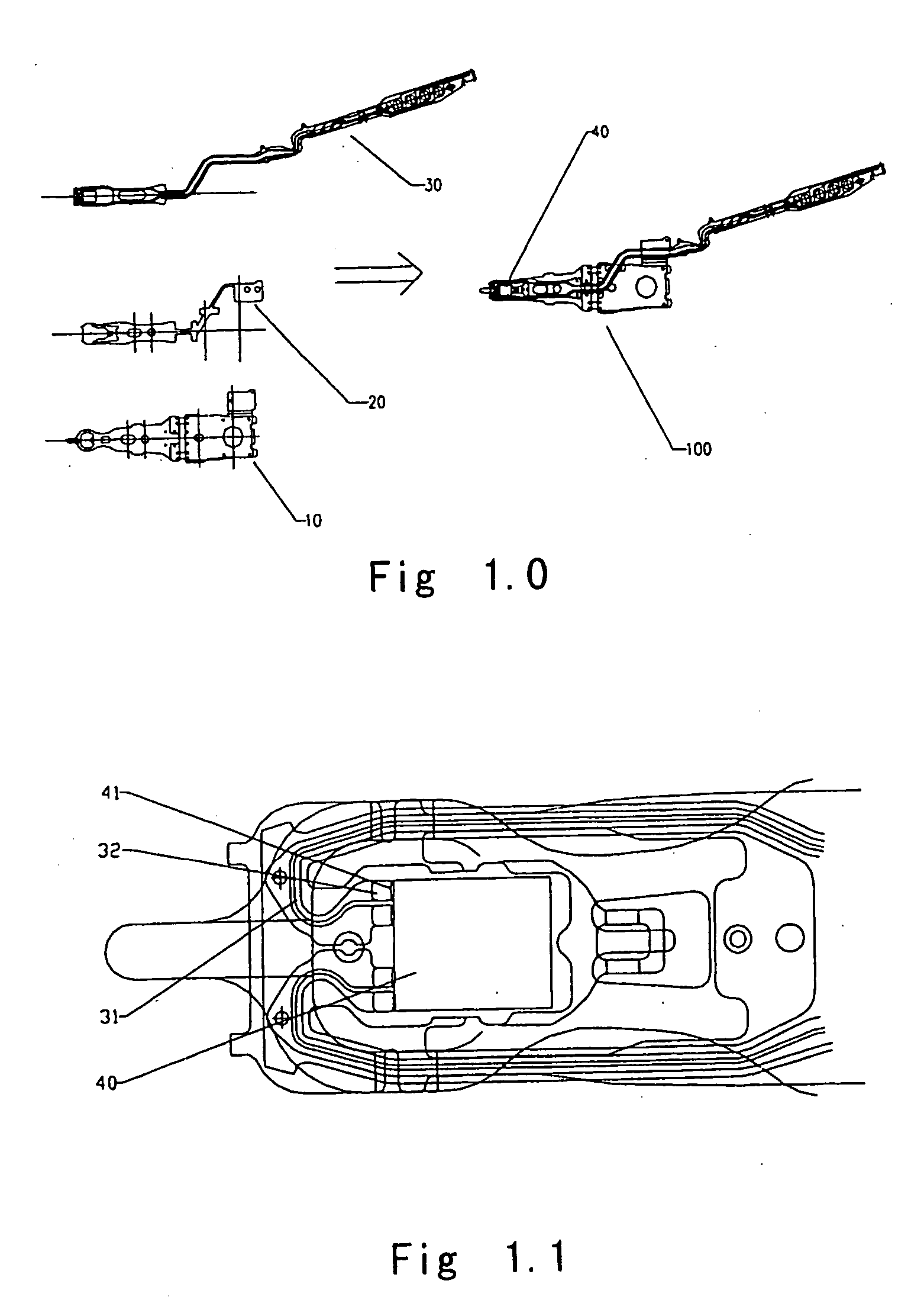
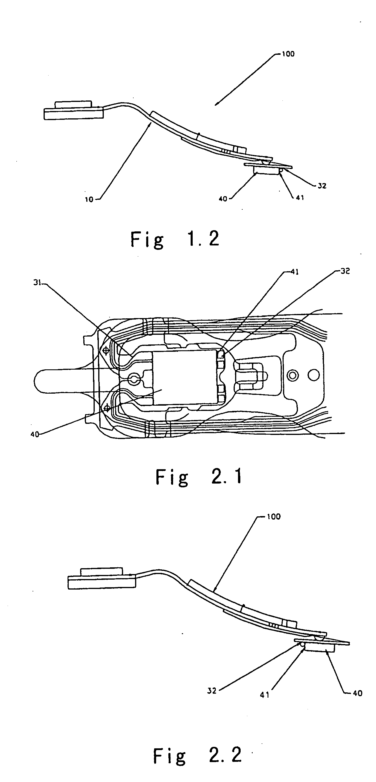
[0044] Firstly, refer to FIG. 2.1 which shows the details of the slider area of a reverse type of HGA in accordance with the present invention. The HGA comprises a suspension 10, a flexure 20, a modified FPC 30 (or flex cable) and a slider 40. Some traces 31 with associated bound pads 32 on the FPC 30 are used as signal lines, and some bump pads 41 on the slider 40 used as slider MR element terminals, as shown in FIGS. 2.1 and 2.2.

[0045] In comparison of the reverse type of HGA shown in FIGS. 2.1 and 2.2 to the conventional HGA shown in FIGS. 1.1 and 1.2, the bonding area of the slider 40 of the reverse type of HGA is provided on the opposite side of the flexure to that of the conventional HGA. With the exception of this, other details of the reverse type of HGA are identical to those of the conventional HGA, and further description of the reverse type of HGA of the present invention is omitted. Nevertheless, bonding a head of the reverse type of HGA by a conventional method is so ...


PUM


Abstract

The present invention relates to a reverse type of HGA and an HGA assembling process for producing the reverse type of HGA. The reverse type of HGA comprises a slider 40, some traces 31 with related bound pads 32 on an FPC 30 used as signal lines, and some bump pads 41 on said slider 40 used as slider MR element terminals; wherein the bonding area of the slider 40 of the reverse type of HGA is provided on opposite side of the flexure to that of the conventional HGA. The HGA assembling process comprises steps: forming a reverse type of FPC 30; mounting a slider 40 to a FPC sheet 300 by epoxy, bound pads being in alignment with bump pads; finishing slider bounding by an SBB machine; cutting the FPC 30 with the slider 40 from the FPC sheet 300; and mounting the FPC 30 with slider 40 to suspension 10 by epoxy.

Description

TECHNICAL FIELD OF THE INVENTION [0001] The present invention generally relates to a new type of FPC (flex print cable) design and its process used in the magnetic head assembly process of HGA production for hard disk drives, and more specifically, to a reverse type of HGA using the new type of FPC design and a process for manufacturing this reverse type of HGA. BACKGROUND OF THE INVENTION [0002] In a conventional head gimbal assembly, a thin film magnetic head (slider) is mechanically attached to a suspension flexure by epoxy bonding. A thin film magnetic head transducer is electrically connected to read / write electronic by printed traces which run the length of the suspension. One end of these traces is ultrasonically bonded to gold plated transducer termination pads on the slider. [0003] U.S. Pat. No. 4,996,623 discloses an integrated suspension fabricated by etching a copper alloy / polyimide / stainless steel laminate, the twisted pairs of wires have been replaced by a copper alloy...

Claims


Application Information

Patent Timeline
IPC IPC(8): G11B5/31G11B5/39G11B5/48G11B5/60
CPCG11B5/3106G11B5/4853G11B5/3903
Inventor SHANG, PING
Owner SHANG PING
Learn More