Image processing apparatus and image processing method

a technology of image processing and image processing, applied in the field of detecting objects, can solve the problems of inability to solve the problem of detection errors, memory consumption and processing cost increase as the resolution rises, and achieve the effect of increasing memory consumption and processing cos

Active Publication Date: 2015-10-01
CANON KK
View PDF1 Cites 17 Cited by
  • Summary
  • Abstract
  • Description
  • Claims
  • Application Information

AI Technical Summary

Benefits of technology

[0008]The present invention has been made in consideration of the above-described problems, and provides a technique for implementing avoidance of a detection error that occurs due to the shift of an input image caused by a motion of an image capturing device without increasing the memory consumption and the processing cost.

Problems solved by technology

When the background model is generated on a pixel basis, the memory consumption and the processing cost increase as the resolution rises.
In the background subtraction method, however, since the camera is assumed to be fixed, the following problems arise if the camera moves due to vibration or the like.
However, this method cannot solve the problems of the memory capacity and the processing cost.
However, since the feature of the block itself changes, the problem of the detection error cannot be solved.
Hence, the conventional techniques cannot avoid a detection error that occurs due to the shift of an input image caused by the motion of the camera without increasing the memory consumption and the processing cost.

Method used


Image

  • Image processing apparatus and image processing method
  • Image processing apparatus and image processing method
  • Image processing apparatus and image processing method

Examples


first embodiment

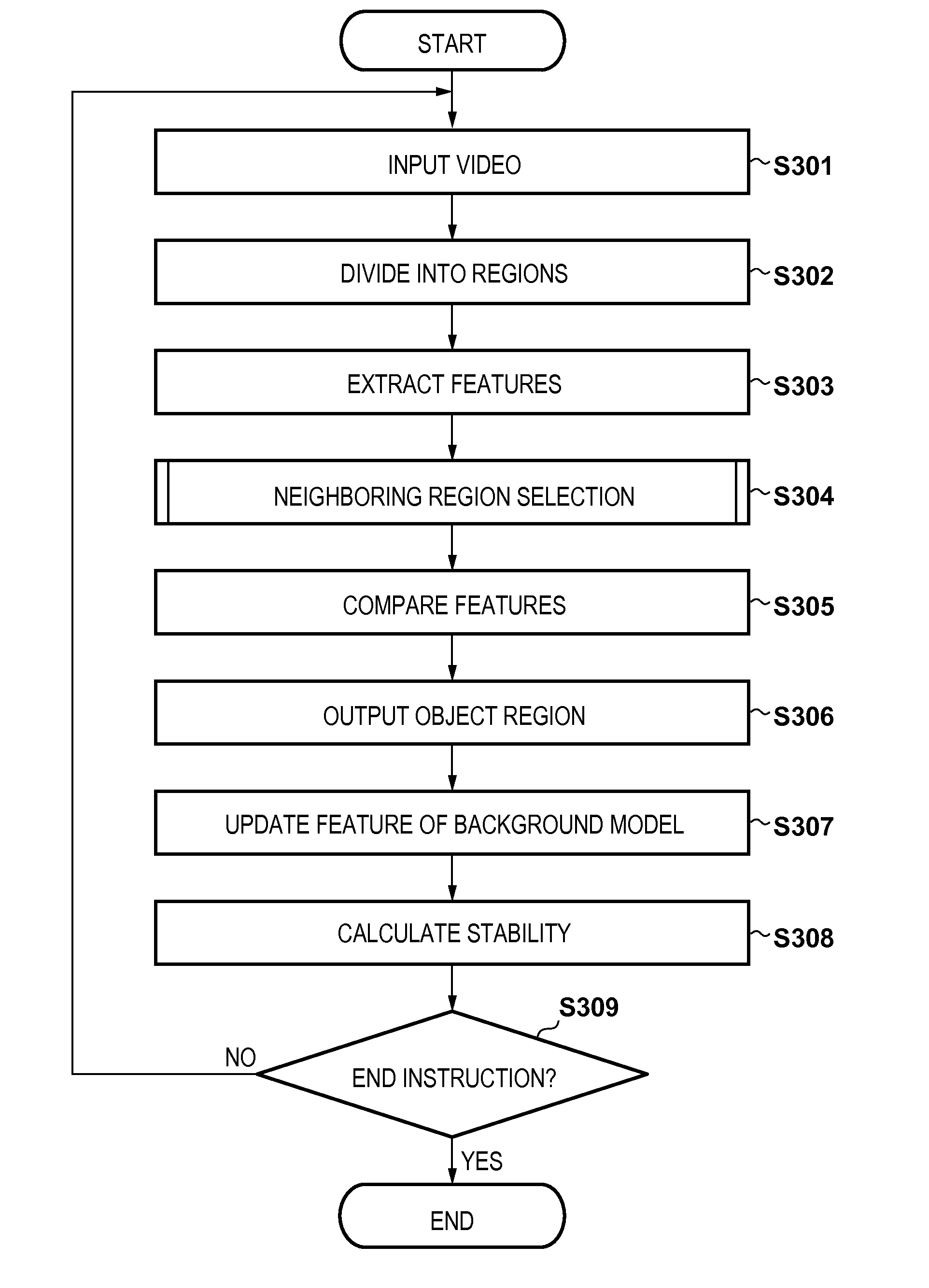
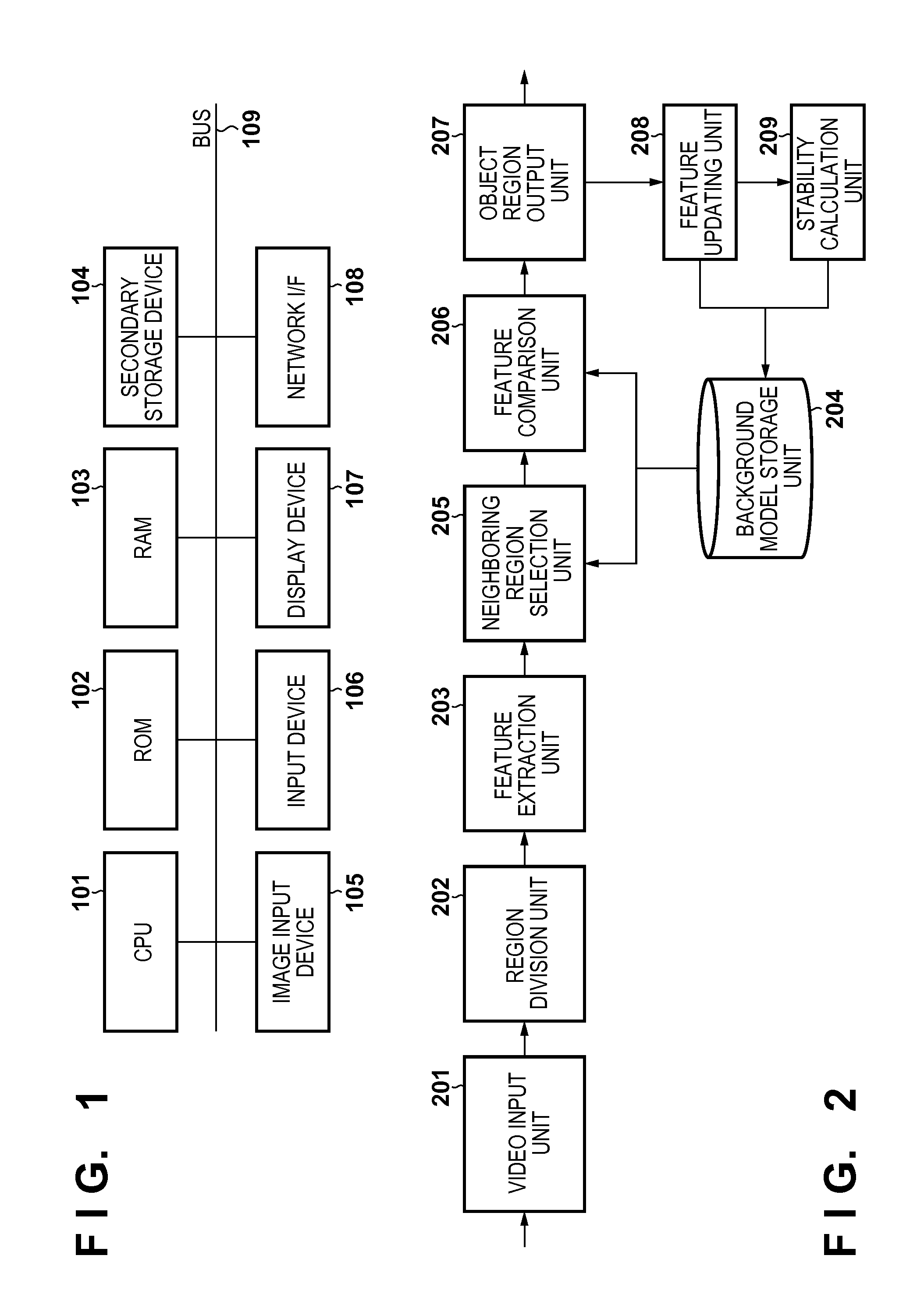
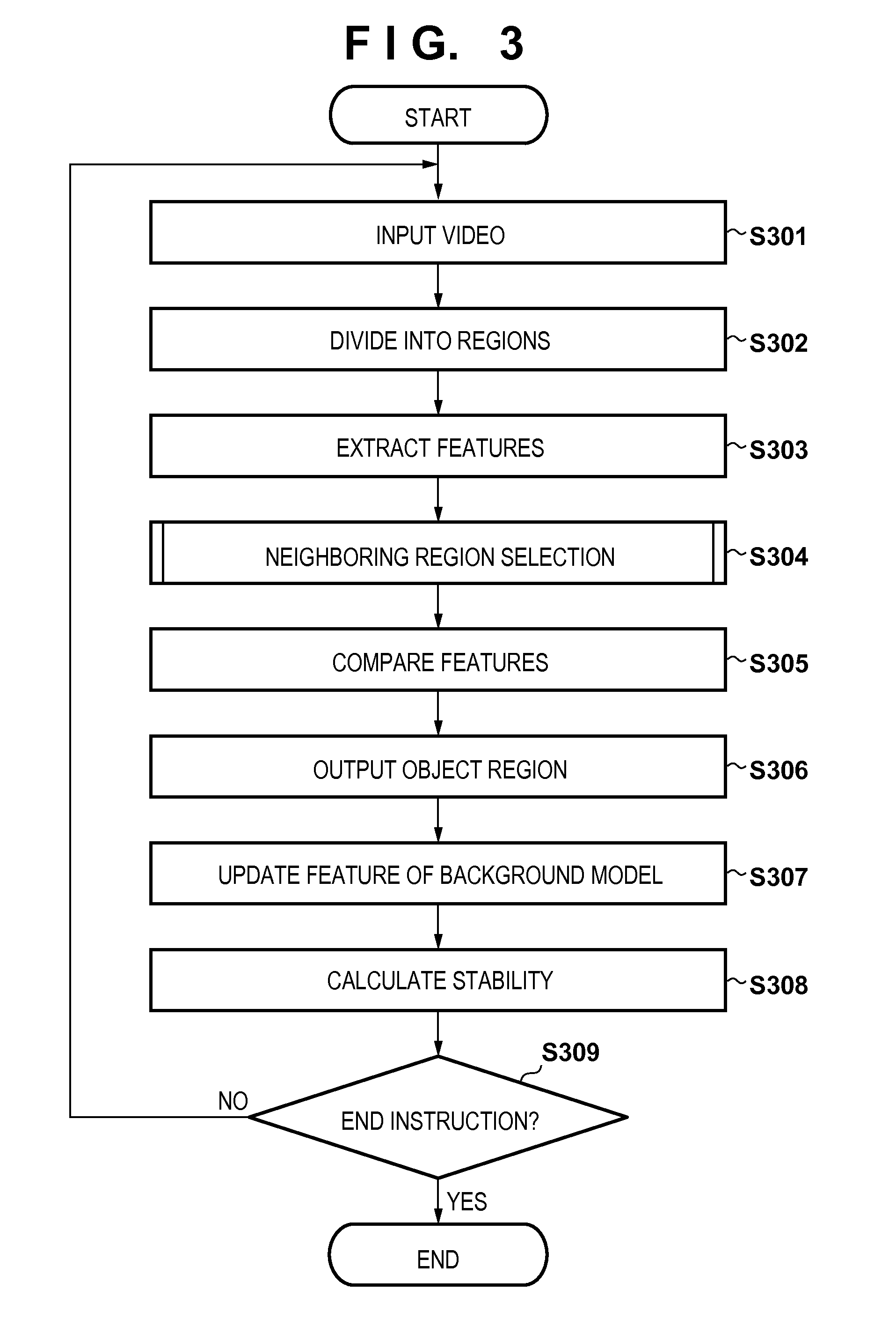
[0018]In this embodiment, a mode of an image processing apparatus that sequentially acquires the images of frames of a moving image and detects a region including an object from the acquired images will be described. First, an example of the functional arrangement of the image processing apparatus according to this embodiment will be explained with reference to the block diagram of FIG. 2. Note that the arrangement shown in FIG. 2 is merely an example, and any other arrangement that implements functions equal to or more than those in FIG. 2 may be employed.

[0019]A video input unit 201 sequentially acquires the images of frames (frame images) of a moving image, and sends the acquired frame images to a region division unit 202 of the subsequent stage. The images of frames may sequentially be sent from a video camera or transferred from an external apparatus by a technique such as streaming.

[0020]The region division unit 202 divides each frame image received from the video input unit 2...

second embodiment

[0068]The functional units shown in FIG. 2 may be stored in one image processing apparatus. However, one or more functional units may be included in an external device. In this case, the image processing apparatus needs to be connected to the external device via a network so as to be data-communicable. The functional units shown in FIG. 2 may be put together on one chip, as a matter of course.

[0069]In addition, the arrangement shown in FIG. 2 can function as an image processing apparatus having the arrangement shown in FIG. 2 if it is a computer including a memory that also functions as a background model storage unit 204, and a processor capable of executing computer programs configured to cause the processor to execute the functions of functional units other than the background model storage unit 204 in FIG. 2. An example of the hardware arrangement of such a computer will be described with reference to the block diagram of FIG. 1. Note that the arrangement shown in FIG. 1 is mere...


PUM


Abstract

An image processing apparatus comprises a video input unit, a region division unit configured to divide an image acquired by the video input unit into a plurality of regions each including pixels of similar attributes, a feature extraction unit configured to extract a feature from each divided region, a background model storage unit configured to store a background model generated from a feature of a background in advance, and a feature comparison unit configured to compare the extracted feature with a feature in the background model and determine for each of the regions whether the region is the background.

Description

BACKGROUND OF THE INVENTION[0001]1. Field of the Invention[0002]The present invention relates to a technique of detecting an object from a moving image.[0003]2. Description of the Related Art[0004]As a technique of detecting an object from an image shot by a camera, a background subtraction method is disclosed. In the background subtraction method, a background image without any object is shot by a fixed camera in advance, and the feature of the image is stored as a background model. After that, the difference between the feature in the background model and the feature in an image input from the camera is obtained, and a different region is detected as a foreground (object).[0005]For example, in patent literature 1 (Japanese Patent No. 2950267), a background model is generated using pixel values as features, and the difference is calculated on a pixel basis, thereby detecting an object. When the background model is generated on a pixel basis, the memory consumption and the processin...

Claims


Application Information

Patent Timeline
Patent Type & Authority Applications(United States)
IPC IPC(8): G06T7/00G06K9/46
CPCG06T7/0081G06K9/4609G06K9/4652G06T2207/20021G06T2207/10016G06T2207/20144G06K9/4642G06T2207/30232G06T7/254G06T7/194G06T7/11G06V10/50G06V10/56G06V10/443G06T7/30
Inventor TOJO, HIROSHIYANO, KOTAROPHAM, TUAN QUANG
Owner CANON KK
Why Eureka
Try Eureka