
Air mass meter with a sensor element

a sensor element and air mass meter technology, applied in the direction of volume/mass flow measurement, measurement devices, instruments, etc., can solve the problems of incorrect measurement values of air mass flow, affecting the measurement results of sensor elements in a particularly disadvantageous way,

Active Publication Date: 2015-10-08
VITESCO TECH GERMANY GMBH
View PDF6 Cites 7 Cited by
  • Summary
  • Abstract
  • Description
  • Claims
  • Application Information

AI Technical Summary

Benefits of technology

[0016]In a subsequent development of the invention, the measuring resistors are arranged in the inner region of the diaphragm. Therefore, the measuring resistors are not affected

Problems solved by technology

During the development of modern air mass meters that operate on the basis of sensor elements embodied as microelectromechanical systems (MEMS) it has become apparent that the measurement results of the sensor elements are influenced in a particularly disadvantageo

Method used


Image

  • Air mass meter with a sensor element
  • Air mass meter with a sensor element
  • Air mass meter with a sensor element

Examples


Embodiment Construction

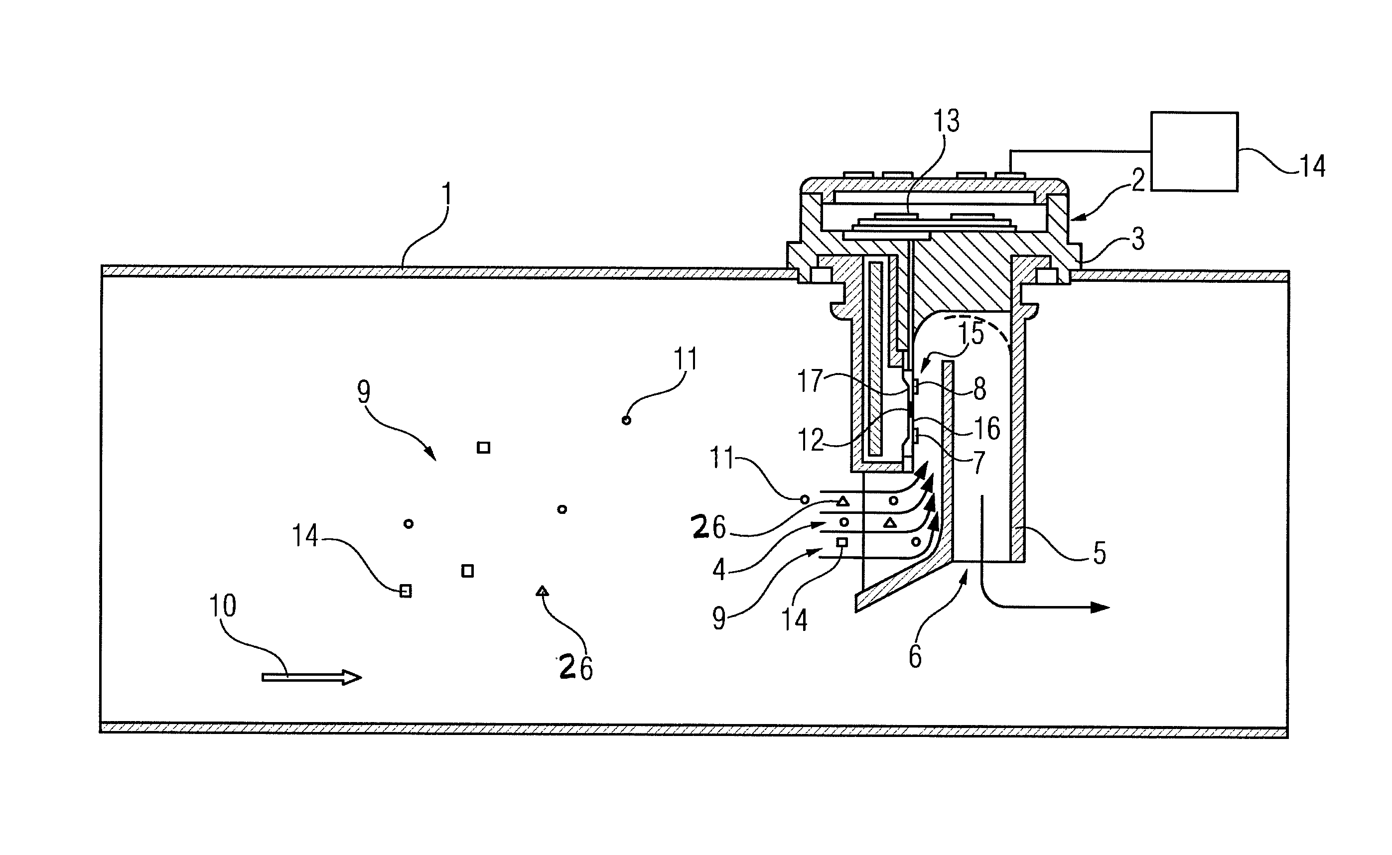
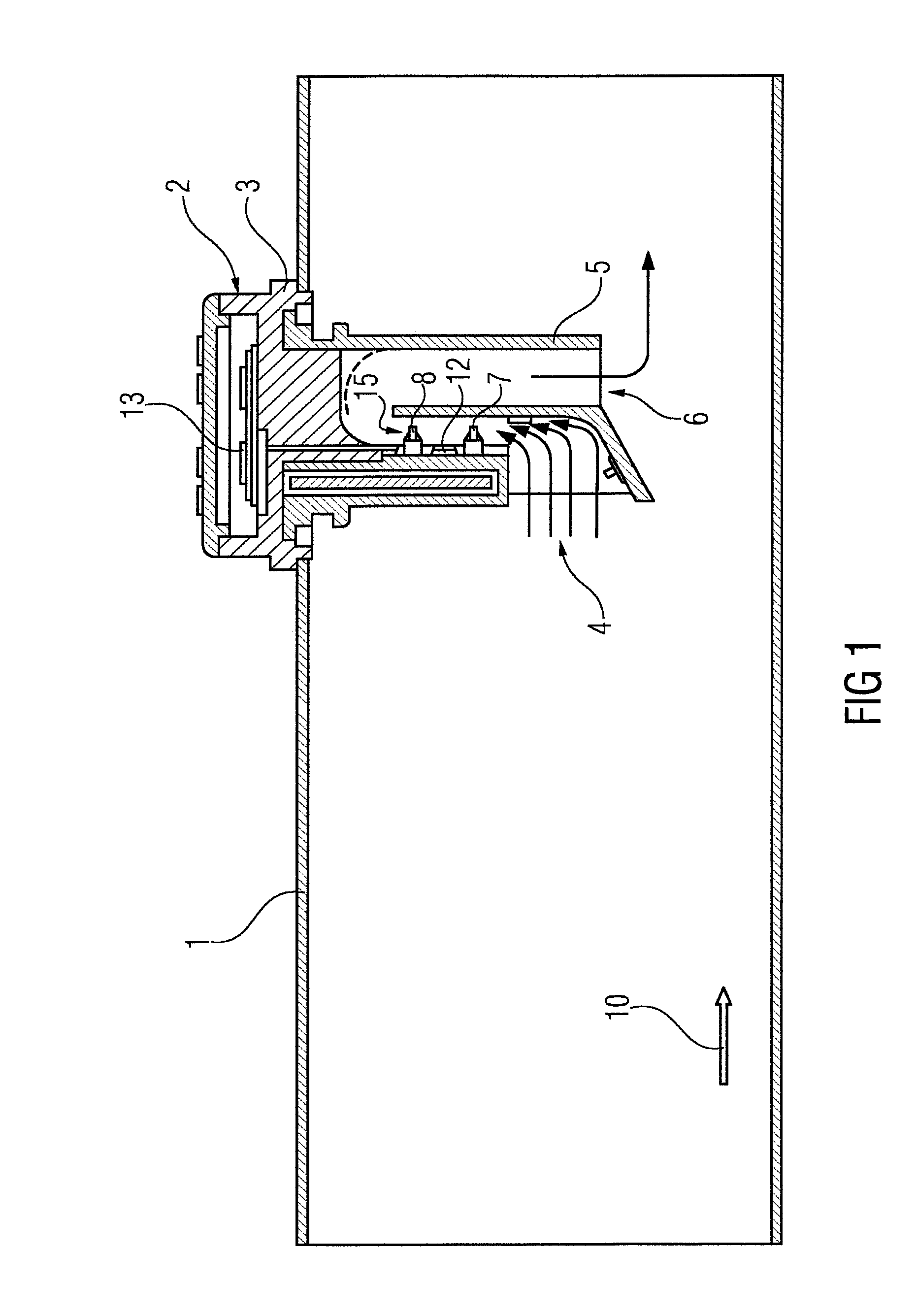
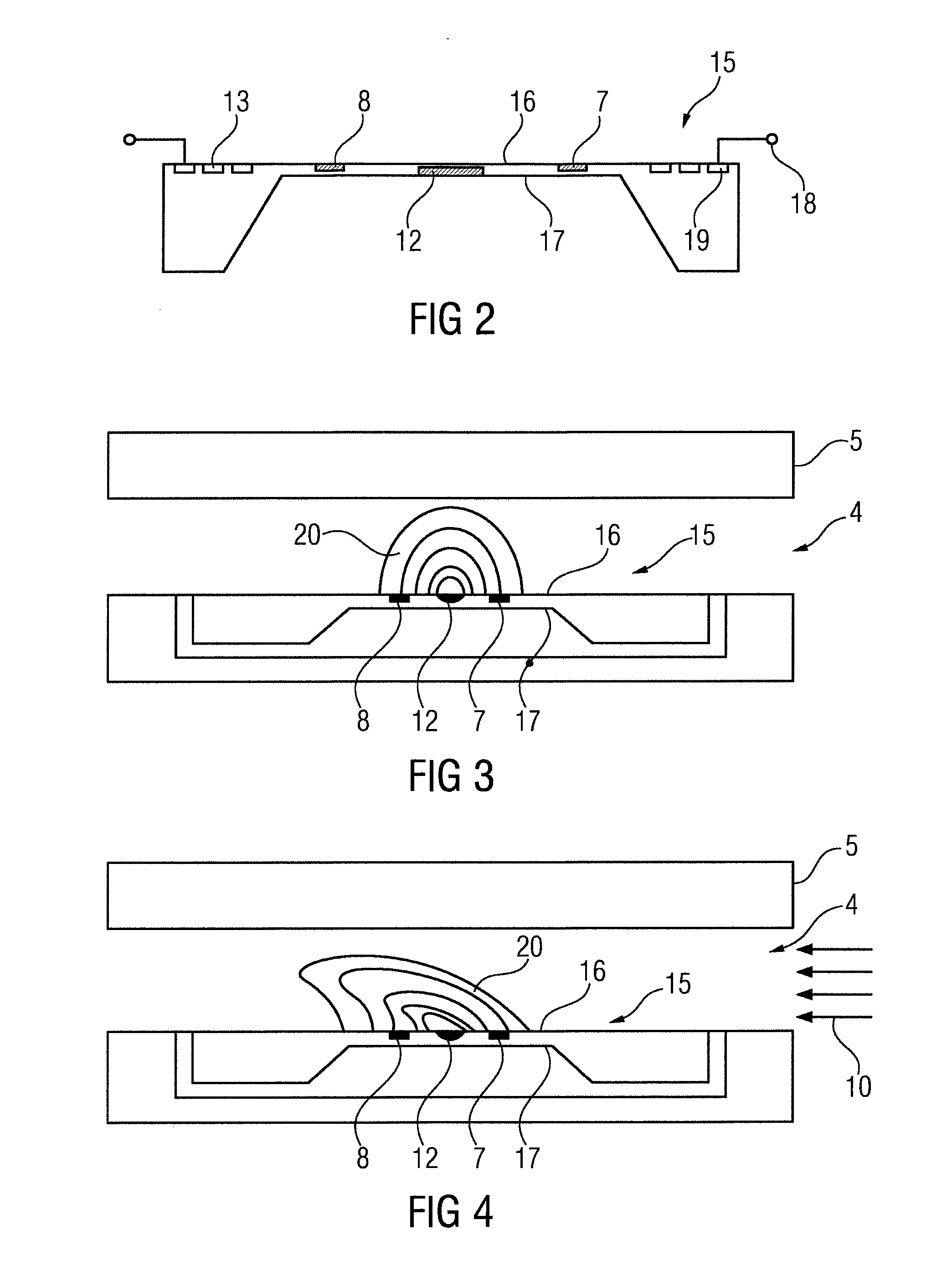
[0026]FIG. 1 shows an air mass meter 2. The air mass meter 2 is embodied in this example as a plug-in finger that is plugged into an intake pipe 1 and is permanently connected to the intake pipe. The intake pipe 1 conducts an air mass flow 10 here, to the cylinders of an internal combustion engine. In order to burn the fuel in the cylinders of an internal combustion engine efficiently, it is necessary to obtain precise information about the available air mass. On the basis of the available air mass it is possible to infer the available oxygen necessary to burn the fuel injected into the cylinders. Furthermore, the air mass meter 2 in FIG. 1 shows a first temperature sensor element 7 and a second temperature sensor element 8. The first temperature sensor element 7 and the second temperature sensor element 8 are arranged at different locations. The temperature sensor elements 7, 8 are generally formed from resistors which adopt different resistance values in accordance with the temper...


PUM


Abstract

An air mass meter has a sensor element, across which an air mass flow to be measured moves. The sensor element is a micro-electro-mechanical system having a membrane, on which a heating element is formed. An electrical measuring resistor and at least two electrical comparison resistors are arranged upstream and downstream of the heating element. A first temperature sensor element is formed with a measuring resistor upstream of the heating element and two comparison resistors arranged downstream of the heating element. The second temperature sensor element is formed with a measuring resistor arranged downstream of the heating element and two comparison resistors arranged upstream of the heating element.

Description

CROSS-REFERENCE TO RELATED APPLICATIONS[0001]This is a U.S. national stage of application No. PCT / EP2013 / 071917, filed on 21 Oct. 2013, which claims priority to the German Application No. DE 10 2012 219 305.7 filed 23 Oct. 2012, the content of both incorporated herein by reference.BACKGROUND OF THE INVENTION[0002]1. Field of the Invention[0003]The invention relates to an air mass meter with a sensor element, wherein an air mass flow to be measured moves over the sensor element, and wherein the sensor element is embodied as a microelectromechanical system which has a diaphragm on which a heating element is embodied, wherein in each case one electrical measuring resistor and at least two electrical comparison resistors are arranged upstream and downstream of the heating element in the direction of the air mass flow, and wherein a first temperature sensor element and a second temperature sensor element are formed by the electrical connection of in each case one measuring resistor to at...

Claims


Application Information

Patent Timeline
IPC IPC(8): G01F1/692
CPCG01F1/692G01F1/684G01F1/6845G01F1/696G01F5/00G01F15/02
Inventor KNITTEL, THORSTENSETESCAK, STEPHEN
Owner VITESCO TECH GERMANY GMBH
Learn More