Robot controller and robot system for moving robot in response to force
- Summary
- Abstract
- Description
- Claims
- Application Information
AI Technical Summary
Benefits of technology
Problems solved by technology
Method used
Image
Examples
first embodiment
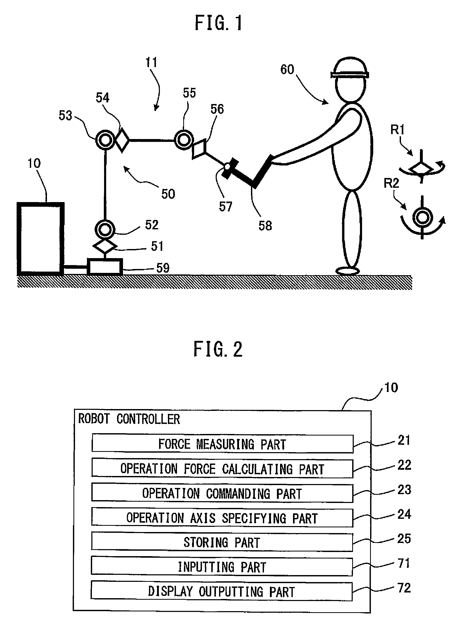
[0045]FIG. 2 is a functional diagram of an example of the configuration of robot controller 10 according the present invention. As shown, robot controller 10 has a force measuring part 21, an operation force calculating part 22, an operation commanding part 23, an operation axis specifying part 24, a storing part 25, an inputting part 71 and a display outputting part 72.
[0046]Force measuring part 21 measures a net force applied to front end 58 of robot 50 by the operator. In this regard, force measuring part 21 compensates for the affect on the force detected by the force sensor due to the gravity or inertia force (including the Coriolis force and gyro effect) of an article such as the tool and the maneuvering unit attached to the force sensor or the gripped workpiece, so as to determine the net force applied to front end 58 of robot 50 by the operator. The affect of the gravity or the inertia force by the article attached to the force sensor may be compensated for by a conventional...
fourth embodiment
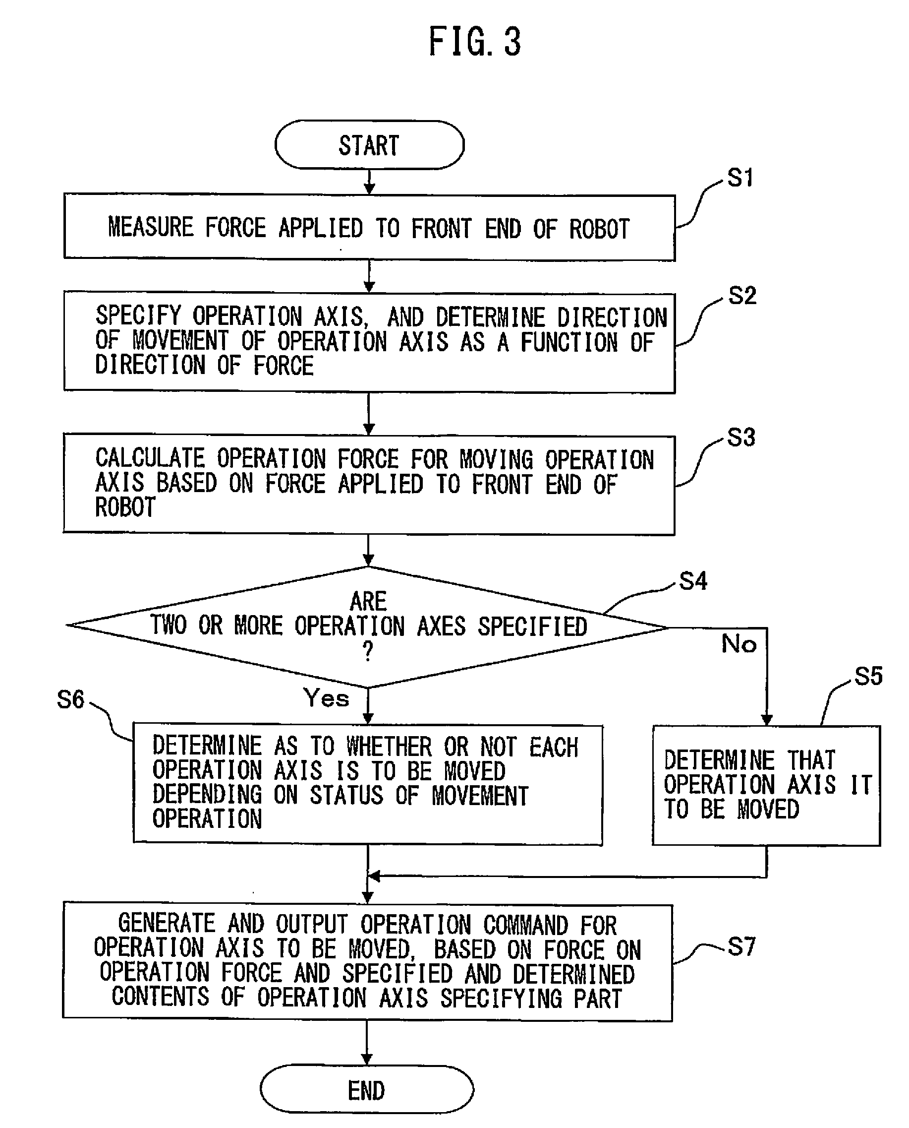
[0110]The process by operation axis specifying part 24 of the robot controller of the fourth embodiment will be explained in detail. In step S2, operation axis specifying part 24 specifies the operation axis to be moved in response to the force, and determines the direction of movement of the operation axis as a function of the direction of the force. In this regard, operation axis specifying part 24 specifies two rotation axes as the operation axes, among the plurality of axes constituting robot 50, wherein the rotation centerlines of the two rotation axes intersect at right angles with each other, regardless of the positions of the plurality of axes.
[0111]By specifying the two rotation axes as the operation axes as explained above, when the direction of the force applied to front end 58 of robot 50 is properly selected, the operation axes can be independently moved, and thus a desired axis can be moved in response to the force. In other words, when only one of the two specified op...
sixth embodiment
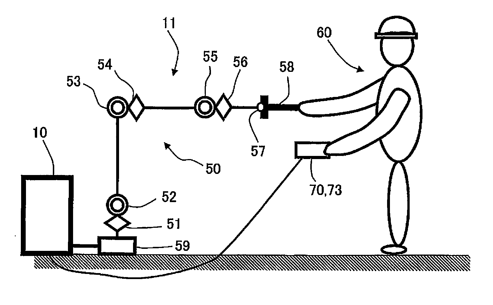
[0123]In the invention, as shown in FIG. 11, robot system 11 includes a teaching operation device 70 for inputting various settings to robot controller 10, and operation axis specifying part 24 specifies the operation axis based on input from teaching operation device 70. Then, teaching operation device 70 selects and inputs a combination of axes capable of being specified as the operation axes.
[0124]As shown in FIG. 11, in robot system 11 including robot 50 controlled by robot controller 10, teaching operation device 70 for inputting various settings to robot controller 10 is connected to robot controller 10. As shown in FIG. 12, teaching operation device 70 may be attached to a proper portion of robot 50 (for example, front end 58 or a link connecting the axes of robot 50), in order that operator 60 does not have to hold teaching operation device 70 when inputting various settings, etc. Further, teaching operation device 70 may have a function for displaying and outputting various...
PUM
 Abstract
Description
Claims
Application Information
 - R&D
- Intellectual Property
- Life Sciences
- Materials
- Tech Scout
- Unparalleled Data Quality
- Higher Quality Content
- 60% Fewer Hallucinations
Browse by: Latest US Patents, China's latest patents, Technical Efficacy Thesaurus, Application Domain, Technology Topic, Popular Technical Reports.
© 2025 PatSnap. All rights reserved.Legal|Privacy policy|Modern Slavery Act Transparency Statement|Sitemap|About US| Contact US: help@patsnap.com


