Electrical connector

Inactive Publication Date: 2010-09-30
JST MFG CO LTD
View PDF2 Cites 8 Cited by
  • Summary
  • Abstract
  • Description
  • Claims
  • Application Information

AI Technical Summary

Benefits of technology

[0036]Since the electrical connector according to the present invention does not include a pair of locking arms in both wings unlike a conventional connector, it is possible to reduce the external shape. In addition, in the electrical connector according to the present invention, the lance for locking the housing to the panel is arranged in the direction orthogonal to the direction of insertion and removal o

Problems solved by technology

Since tips of the locking arms are open in the connector of the panel attachment type according to the prior art, there has been a drawback that load is imposed on the ends of the locking arms due to insertion and removal operations of the counterpart connector.
On the other hand, if the ends of the locking arms are reinforced, there has been a drawback in that insertion through the opening of the panel becomes difficult.
However, since the connector according to Patent Document 1 includes the pair of locking arms in both wings

Method used


Image

  • Electrical connector
  • Electrical connector
  • Electrical connector

Examples


first embodiment

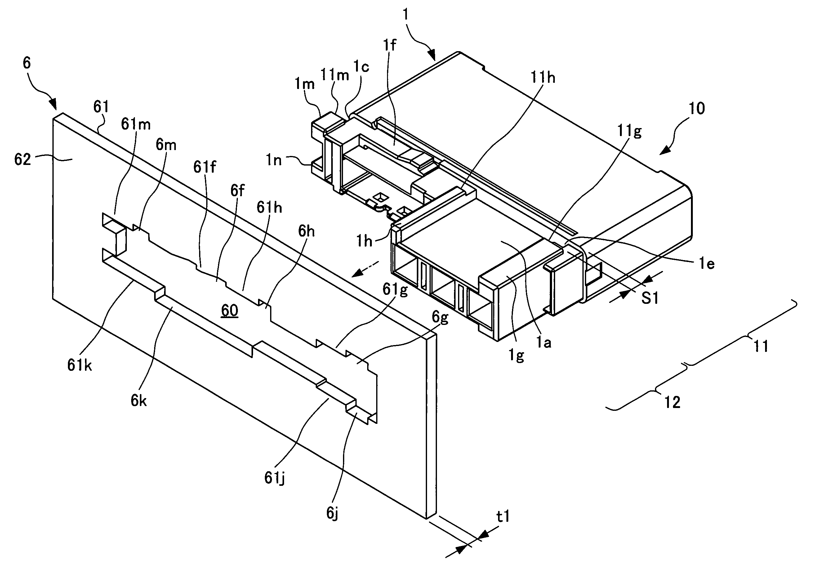
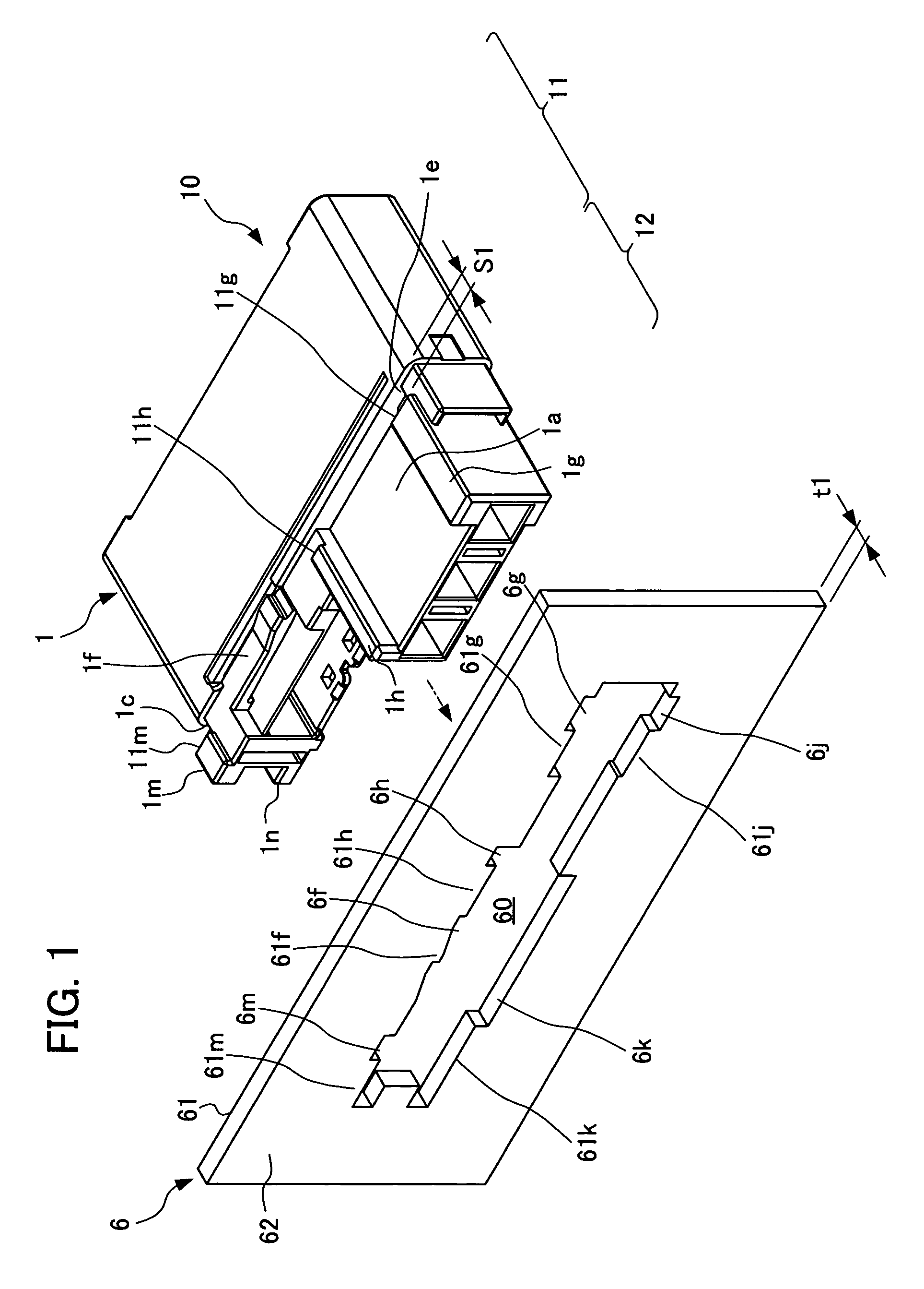
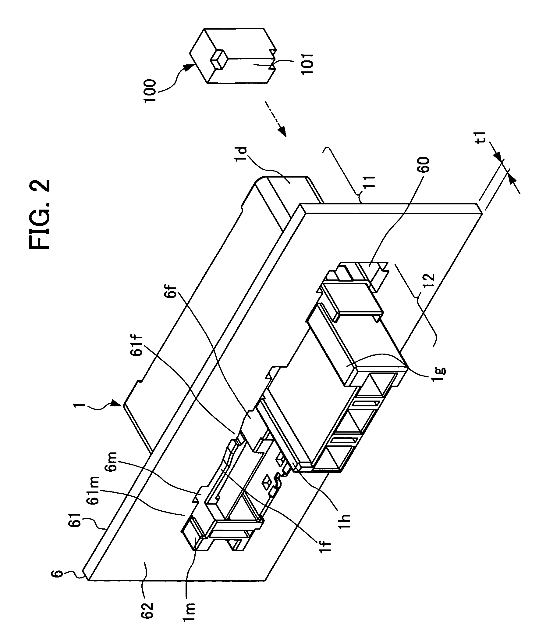
[0060]Firstly, a configuration of an electrical connector (hereinafter referred to as a connector) according to a first embodiment of the present invention is described. FIGS. 1 to 4 are perspective views each showing an appearance of a housing provided to an electrical connector according to the first embodiment of the present invention, where FIG. 1 shows a state in which a thick panel is arranged opposite thereto; FIG. 2 shows a state in which the thick panel is attached to the housing from a front face; and furthermore, FIG. 3 shows a state in which a thin panel is arranged opposite thereto; and FIG. 4 shows a state in which the thin panel is attached to the housing from the front face.

[0061]FIG. 5 is a perspective view in which the appearance of the electrical connector according to the first embodiment of the present invention is viewed substantially from the top side. FIG. 6A is an enlarged view of a main portion of the left side of FIG. 5, and FIG. 6B is an enlarged view of ...

second embodiment

[0103]Next, operations of a connector according to a second embodiment of the present invention are described. FIG. 17 is a perspective view showing an appearance of a housing provided to an electrical connector according to a second or third embodiment of the present invention, and showing a state in which a thick panel is arranged opposite thereto.

[0104]FIG. 18 is a perspective view showing an appearance of the housing provided to the electrical connector according to the second or third embodiment of the present invention, and showing a state in which a thin panel is arranged opposite thereto. FIG. 19 is a perspective view in which the appearance of the housing provided to the electrical connector according to the second or third embodiment of the present invention is viewed substantially from the bottom side.

[0105]With reference to FIG. 17, a connector 20 according to the second embodiment of the present invention includes a housing 2 of a rear face attachment type to be attache...

third embodiment

[0146]Next, a configuration and operations of a connector according to a third embodiment of the present invention are described.

[0147]With reference to FIG. 1 or 2 and FIG. 17, a connector 30 according to the third embodiment of the present invention includes a housing 3 of a front face attachment type to be attached to the front face 61 of the thick panel 6. With reference to FIG. 3 or 4 and FIG. 17, the housing 3 can also be attached to the front face 71 of the thin panel 7.

[0148]With reference to FIG. 17, the connector 30 according to the third embodiment of the present invention includes the housing 3 of a rear face attachment type to be attached from the rear face 42 toward the front face 41 of the thick panel 4. With reference to FIG. 18, the housing 3 can also be attached from the rear face 52 toward the front face 51 of the thin panel 5.

[0149]The rear portion 32 of the housing 3 shown in FIGS. 17 to 19 is configured similarly to the rear portion 12 of the housing 1. Moreove...


PUM


Abstract

A connector includes a housing to be attached to a front face of a panel. A panel has a mounting opening through which a rear portion of the housing is inserted. The rear portion of the housing has a lance extending in a direction parallel to the front face of the panel. The mounting opening has a concave portion through which the lance is inserted. When the housing is moved in a first direction along the front face of the panel, a locking piece that continues to a concave portion locks the tip of the lance such that the housing is difficult to move in a second direction.

Description

[0001]This application is based on and claims the benefit of priority from Japanese Patent Applications No. 2009-075422, filed on 26 Mar. 2009, the content of which is incorporated herein by reference.BACKGROUND OF THE INVENTION[0002]1. Field of the Invention[0003]The present invention relates to an electrical connector. In particular, the present invention relates to a structure of an electrical connector (hereinafter referred to as a connector) of a panel attachment type to be attached to a board, a panel, a frame and the like.[0004]2. Related Art[0005]Generally, as a connector of a panel attachment type, a rectangular connector having a rectangular joining face is known. For example, such a rectangular connector includes a pair of cantilevered locking arms in both wings of a housing. It is configured such that, when the housing is inserted through a rectangular opening provided to a panel, the pair of locking arms is locked to the opening of the panel, thereby fixing the connecto...

Claims


Application Information

Patent Timeline
IPC IPC(8): H01R13/73
CPCH01R13/743
Inventor USHIRO, YUTAKAMASAKI, KATSUYUKI
Owner JST MFG CO LTD
Why Eureka
Try Eureka