LED lamp

a technology of led lamps and led lamps, which is applied in the field of led lamps, can solve the problems of poor heat dissipation and sealing properties of inconvenient disassembly and installation of power supplies, and inability to easily disassemble led lamps in prior art, etc., and achieves convenient disassembly and installation, good appearance, and convenient opening.

Inactive Publication Date: 2015-10-15
SHENZHEN YAORONG TECH
View PDF7 Cites 21 Cited by
  • Summary
  • Abstract
  • Description
  • Claims
  • Application Information

AI Technical Summary

Benefits of technology

[0042]1) Since the power supply of LED lamp is installed at the back of the radiator, one end of the power supply box is movably connected with one end of the back of the radiator, it is convenient to open and is easy for dismounting and installing the power supply;
[0043]2) The LED lamp comprises the lens module plate that takes the integrated design for waterproofing and optical purpose and is concise and in good appearance, which does not use the glass plate to separate the lens from the external part, and it may still achieve better waterproof effect;
[0044]3) Lens in the lens module plate is the polarized light distribution lens, which can bring about polarized light distribution applicable to lighting for large angle and scope so as to disperse the light for irradiation and enlarge the lighting area;
[0045]4) The radiator is provided with the holes for interconnecting the lower and upper parts of the radiator to form convection, which is convenient for heat exchange, and achieve good heat dissipation; and
[0046]5) The power supply is provided with a lightning arrester, which can improve the safety so as to extend service life of the LED lamp.

Problems solved by technology

The LED lamp in prior art is poor in heat dissipation and sealing property, and the illumination of the LED lamp in prior art is also not homogenous.
For the existing LED lamps, the power supply is not easily dismounted and installed.
Once it requires test, repair or replacement, it is necessary to open the upper and lower covers of the LED lamp to take out the power supply, which is fairly troublesome and time-consuming.
Although it can achieve the waterproof purpose, the structure is not concise.
In addition, the existing LED lamp have poor heat dissipation performance.

Method used


Image

  • LED lamp
  • LED lamp
  • LED lamp

Examples


Embodiment Construction

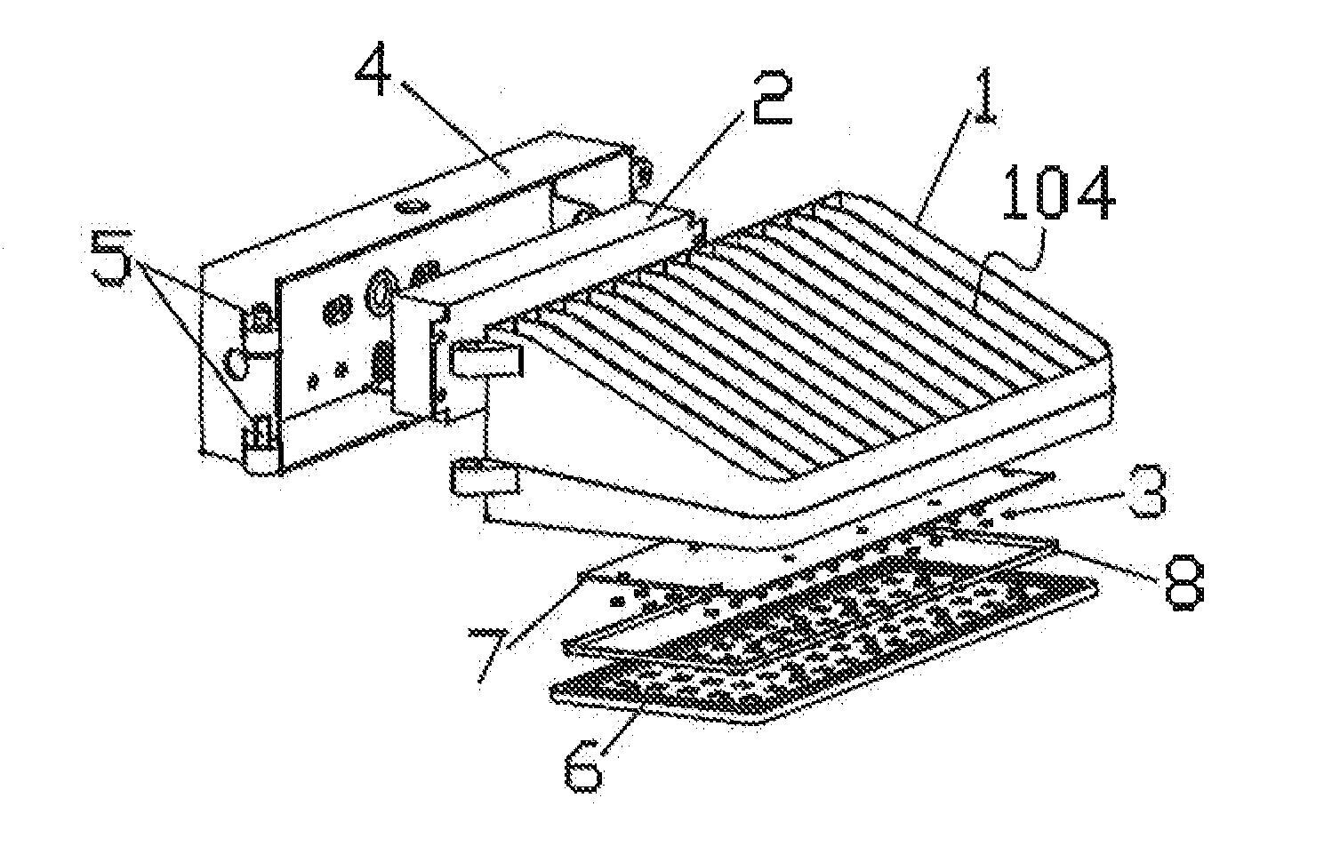
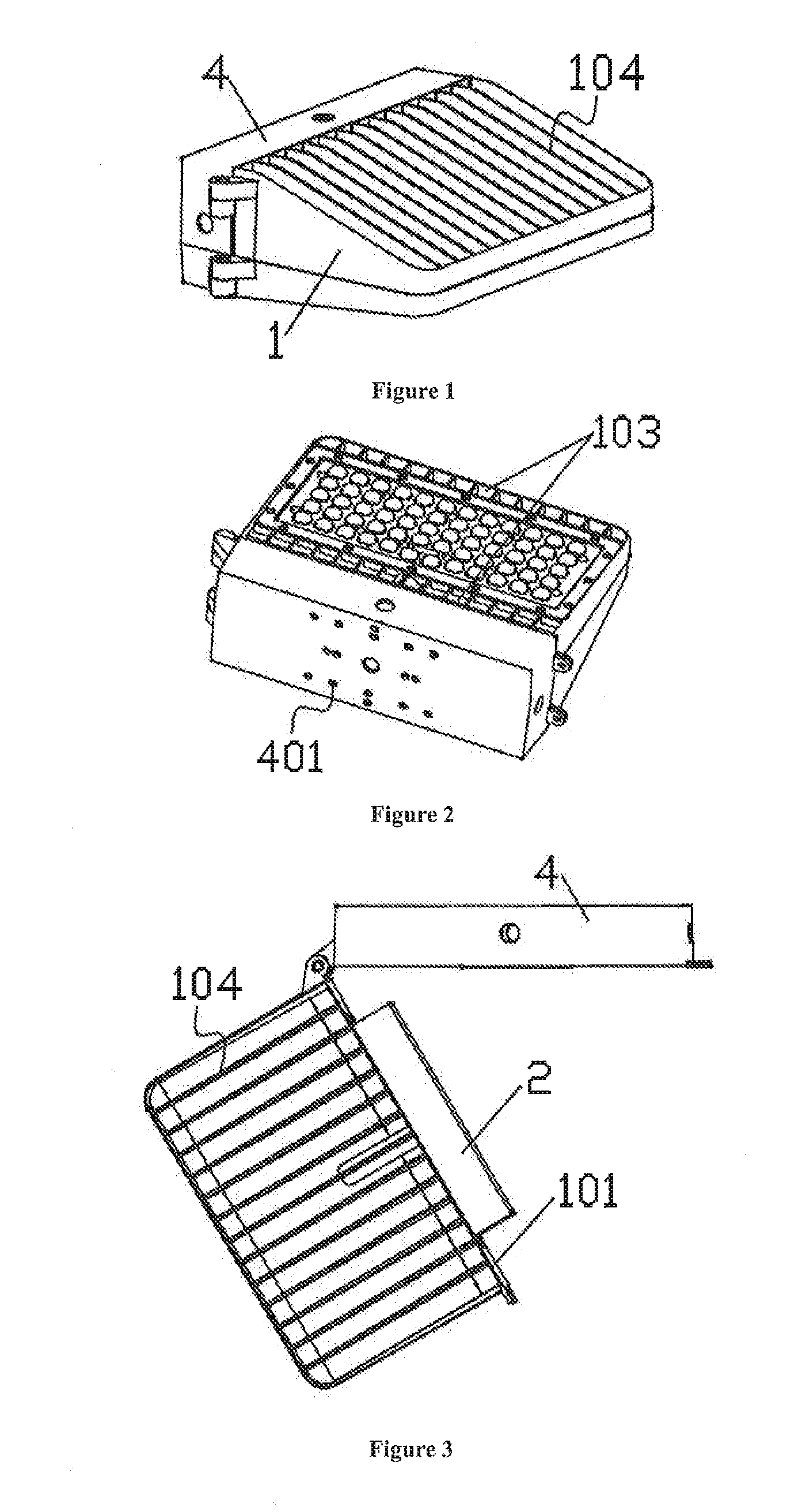
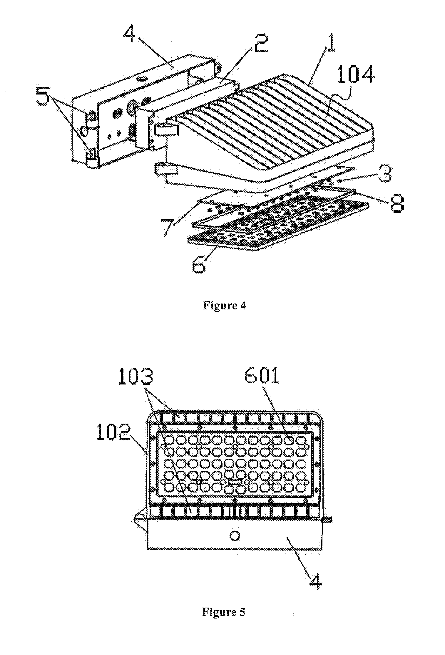
[0052]To better understand this invention, detailed description of the present invention are set forth below in conjunction with the accompany drawings. Referring to FIGS. 1, 2, 3, 4 and 5, an LED lamp of this invention mainly comprise a radiator 1, a power supply 2, a plurality of LED light sources 3. The power supply 2 is electrically connected with the LED light sources 3, the power supply 2 is installed at back 101 of the radiator 1, the power supply box 4 covers the power supply 2 and is fixedly secured to the back 101 of the radiator 1. One end of the power supply box 4 is movably connected with one end of the back 101 of the radiator 1 by, for example, a the rotating shaft 5, the other end of the power supply box 4 is fixed to the other end of the back 101 of the radiator 1 by a fastener (not shown in the figures). Based on such designs, it is convenient for opening the power supply box and is easy for dismounting and installing the power supply.

[0053]In order to install the ...


PUM


Abstract

This invention discloses a LED lamp, which comprises a radiator; a power supply having a power supply box; and a plurality of LED light sources electrically connected with the power supply; wherein the power supply is installed at the back of the radiator; and the power supply is covered by the power supply box which is fixedly secured on the back of the radiator. One end of the power supply box is movably connected with one end of the back of the radiator, and the other end of the power supply box is fixedly secured to the other end of the back of the radiator by fasteners. The LED lamp further comprises a lens module plate covering the LED light sources and sealing by a waterproof ring. This LED lamp can be easily dismounted and installed, whose structure is concise. And The LED lamp has the advantages of good waterproof effect and good heat dissipation, which can be extensively utilized for lighting.

Description

TECHNICAL FIELD OF THE INVENTION[0001]The instant invention relates to the field of light fixture, and more particularly, to an LED lamp.BACKGROUND OF THE INVENTION[0002]The LED lamp in prior art is poor in heat dissipation and sealing property, and the illumination of the LED lamp in prior art is also not homogenous.[0003]For the existing LED lamps, the power supply is not easily dismounted and installed. Once it requires test, repair or replacement, it is necessary to open the upper and lower covers of the LED lamp to take out the power supply, which is fairly troublesome and time-consuming.[0004]In addition, the lenses in the existing LED lamp are individual lens, and the glass plate is used for separating the lens from the external part and preventing contact. Although it can achieve the waterproof purpose, the structure is not concise.[0005]In addition, the existing LED lamp have poor heat dissipation performance.SUMMARY OF THE INVENTION[0006]The object of the invention is to s...

Claims


Application Information

Patent Timeline
Patent Type & Authority Applications(United States)
IPC IPC(8): F21V23/02F21S8/00F21K99/00F21V31/00F21V29/76F21V5/04
CPCF21V23/023F21V29/76F21V5/048F21Y2101/02F21V31/005F21S8/036F21K9/50F21V23/009F21V29/763F21Y2115/10
Inventor YU, HUAN HUANYONG, YING
Owner SHENZHEN YAORONG TECH
Why Eureka
Try Eureka