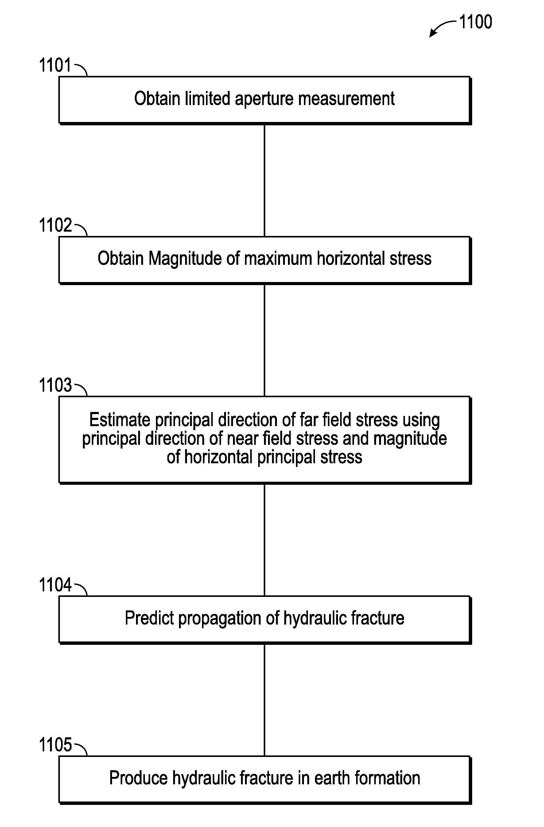
Predicting hydraulic fracture propagation
a technology of hydraulic fracture and propagation, applied in the field of predicting hydraulic fracture propagation, can solve the problem of non-uniform stress-induced anisotropy in such a medium
- Summary
- Abstract
- Description
- Claims
- Application Information
AI Technical Summary
Benefits of technology
Problems solved by technology
Method used
Image

Examples
Embodiment Construction
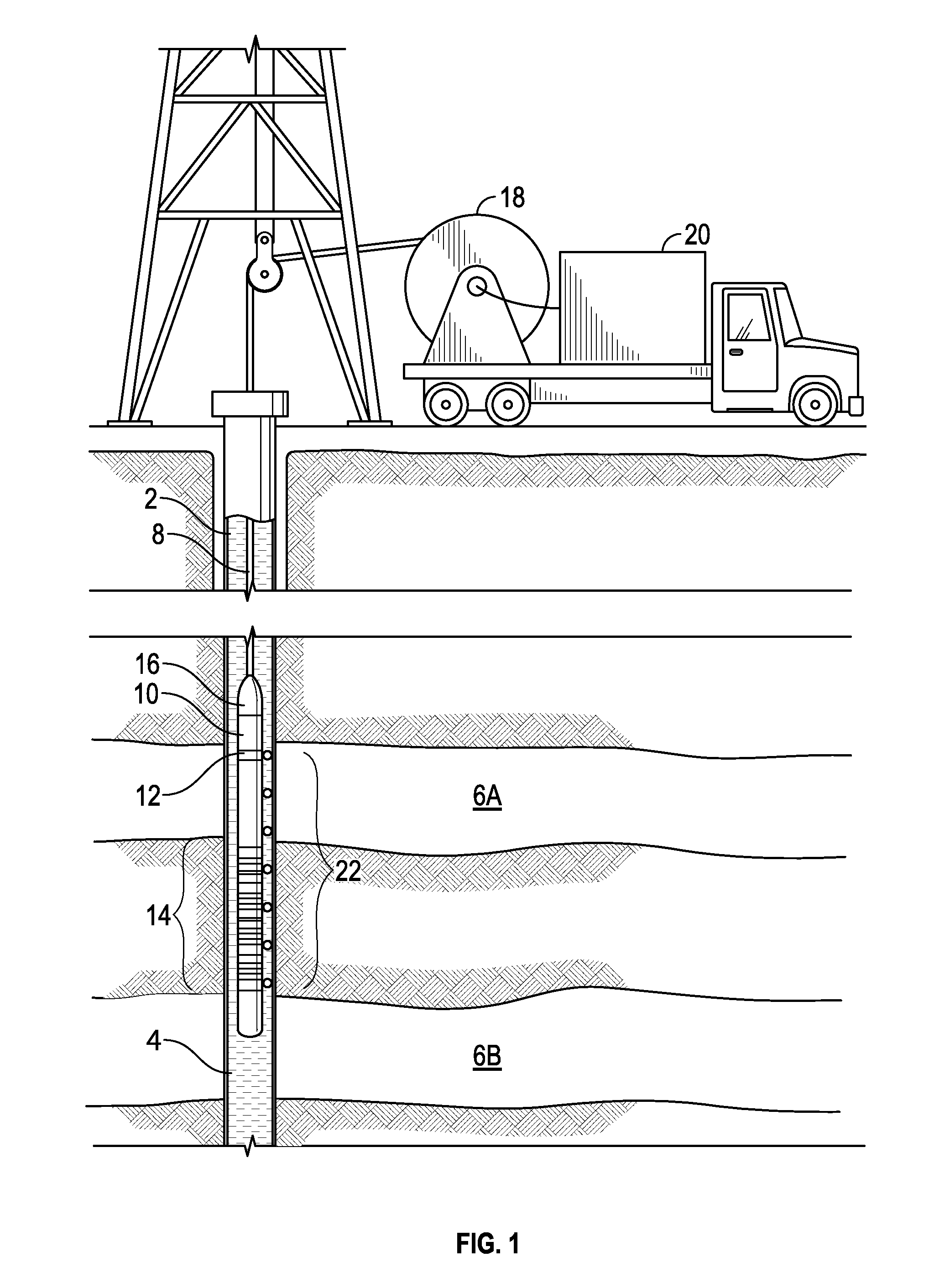
[0032]The present disclosure is discussed with reference to specific logging instruments that may form part of a string of several logging instruments for conducting wireline logging operations. It is to be understood that the choice of the specific instruments discussed herein is not to be construed as a limitation and that the method of the present disclosure may also be used with other logging instruments.
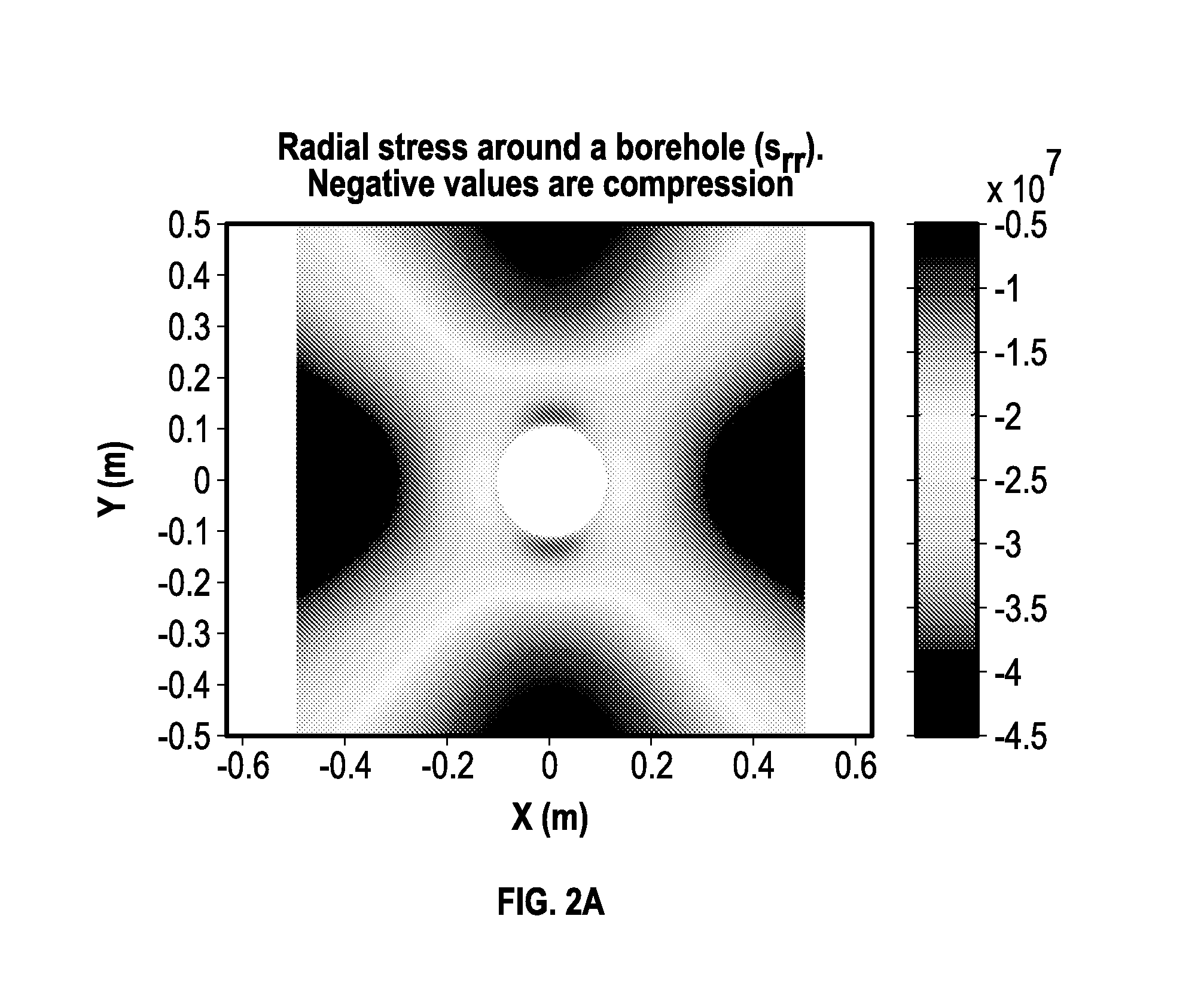
[0033]The orientation of subsurface, or “in-situ,” stresses of a formation are indicative of the direction of fracture propagation of an induced hydraulic fracture. Stresses acting on a subsurface formation at a distance greatly removed from the site of a hydraulic fracturing operation are known as “far-field” stresses. These stresses may be resolved into a maximum (or “greatest”) far-field stress an intermediate far-field stress and a minimum (or “least”) far-field stress. The directions in which these stresses act are referred to as the “principal stress directions” or the “di...
PUM
 Abstract
Description
Claims
Application Information