Transmission method and reception methodof downlink signal and channel, terminal thereof, and base stattion thereof.

a technology of downlink signal and reception method, applied in the field of transmission method and reception method of downlink signal and channel, a ue thereof, can solve the problem that the limited control region may not be enough to include all control channels, and achieve the effect of efficient transmission of control information

Active Publication Date: 2015-10-22
IUCF HYU (IND UNIV COOP FOUNDATION HANYANG UNIV)
View PDF13 Cites 68 Cited by
  • Summary
  • Abstract
  • Description
  • Claims
  • Application Information

AI Technical Summary

Benefits of technology

[0021]According to the above-described present invention, a transmission method and reception method of an aperiodic sounding reference signal, a UE thereof, and a base station thereof transmit a narrow-banded aperiodic sounding reference signal whi

Problems solved by technology

However, a limited control region may not

Method used


Image

  • Transmission method and reception methodof downlink signal and channel, terminal thereof, and base stattion thereof.
  • Transmission method and reception methodof downlink signal and channel, terminal thereof, and base stattion thereof.
  • Transmission method and reception methodof downlink signal and channel, terminal thereof, and base stattion thereof.

Examples


embodiment 1

Generate SRS Sequence

[0085]FIG. 6 is a signal flow diagram illustrating a method of transmitting an SRS according to an embodiment.

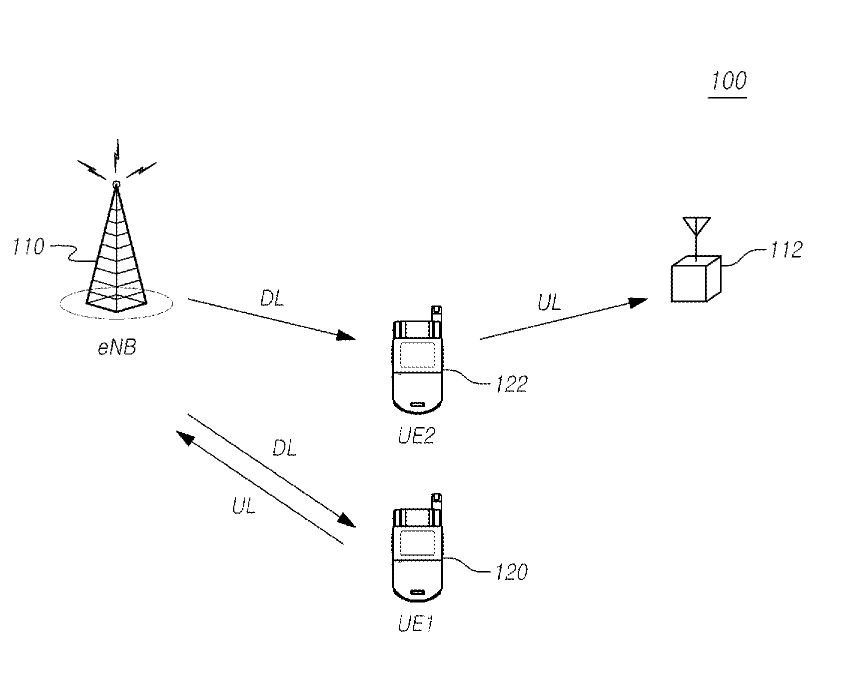
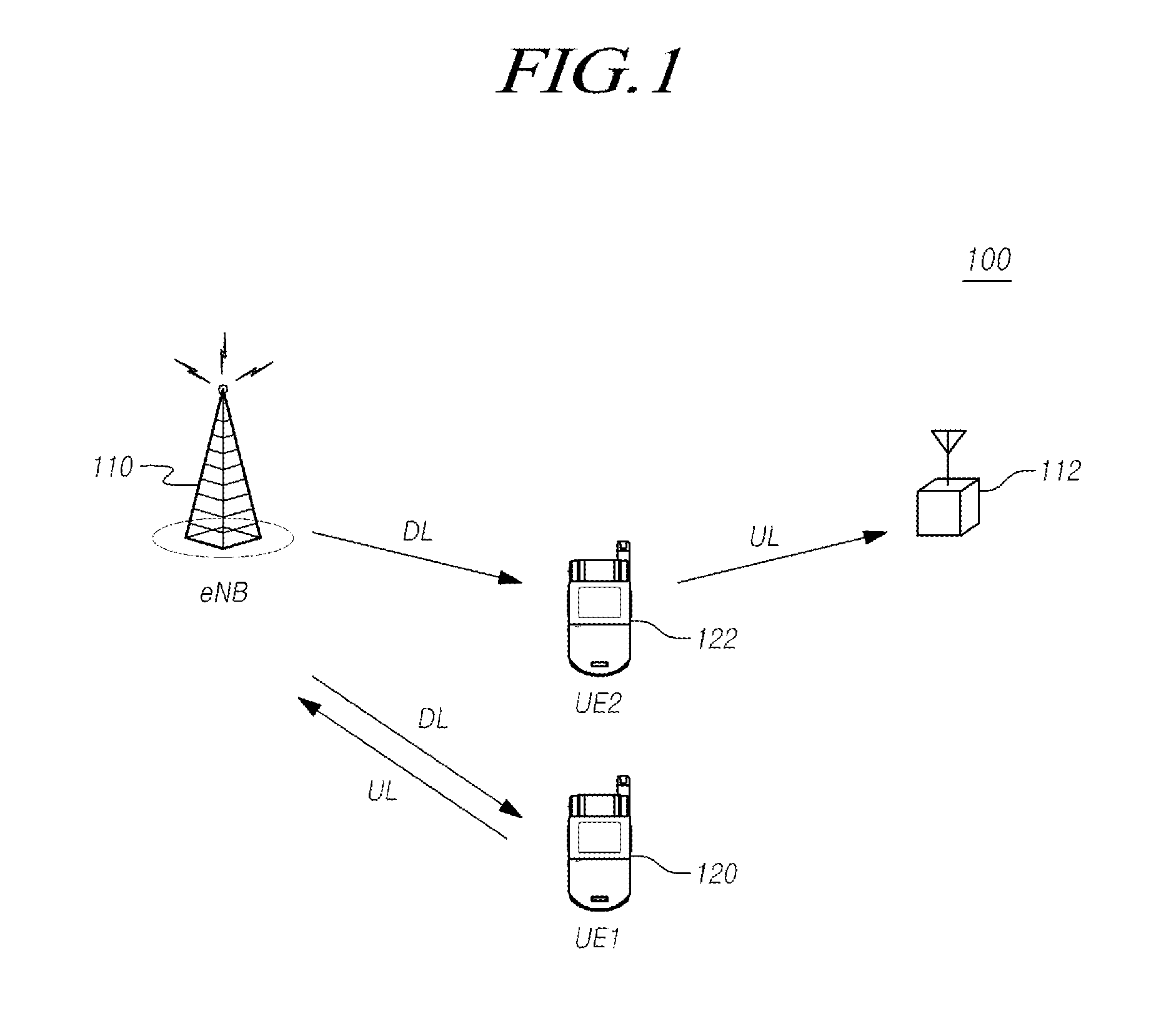
[0086]Referring to FIG. 6, the eNB 110, which is one of the transmission / reception points, transmits UE-specific configuration information for uplink transmission to the UE 120 belonging to the eNB 110 (S610). In operation S610, the UE 120 receives the UE-specific configuration information for uplink transmission.

[0087]The UE-specific configuration information for uplink transmission includes a UE-specific parameter by which the UE 120 belonging to the eNB 110 is UE-specifically configured for uplink transmission.

[0088]In detail, a PUSCH, a reference signal (PUSCH DM-RS) associated with the PUSCH, a PUCCH, and a reference signal (PUCCH DM-RS) associated with the PUCCH are independent of each other, a sequence independent of a PUCCH and PUSCH sequence is generated as an SRS sequence, and uplink transmission to a transmission / reception point can be perform...

embodiment 2

Frequency Hopping of One Aperiodic SRS

[0147]A specific sub-frame, from which an SRS is transmitted, can be configured periodically or aperiodically.

[0148]As described above, in order to allow a UE to transmit a periodic SRS or a trigger type 0 SRS, parameters srs-SubframeConfig and ISRS for determining a sub-frame from which an SRS is transmitted, parameters CSRS, BSRS, and nRRC for determining a resource block to which an SRS is transmitted, a parameter kTC for determining a sub-carrier to which an SRS is allocated, a parameter nSRScs for determining a cyclic shift of an SRS, and the number of antenna ports can be transmitted from a transmission port to the UE through high layer signaling such as RRC signaling.

[0149]Meanwhile, an SRS can be transmitted from an aperiodically-configured specific sub-frame among cell-specific SRS transmittable sub-frame determined by Table 1 and Table 2, and can be called an aperiodic SRS or a trigger type 1 SRS.

[0150]In this case, the SRS is aperiodi...

embodiment 3

SRS Power Control

[0162]FIG. 11 is a flowchart illustrating an uplink power control method according to yet another embodiment.

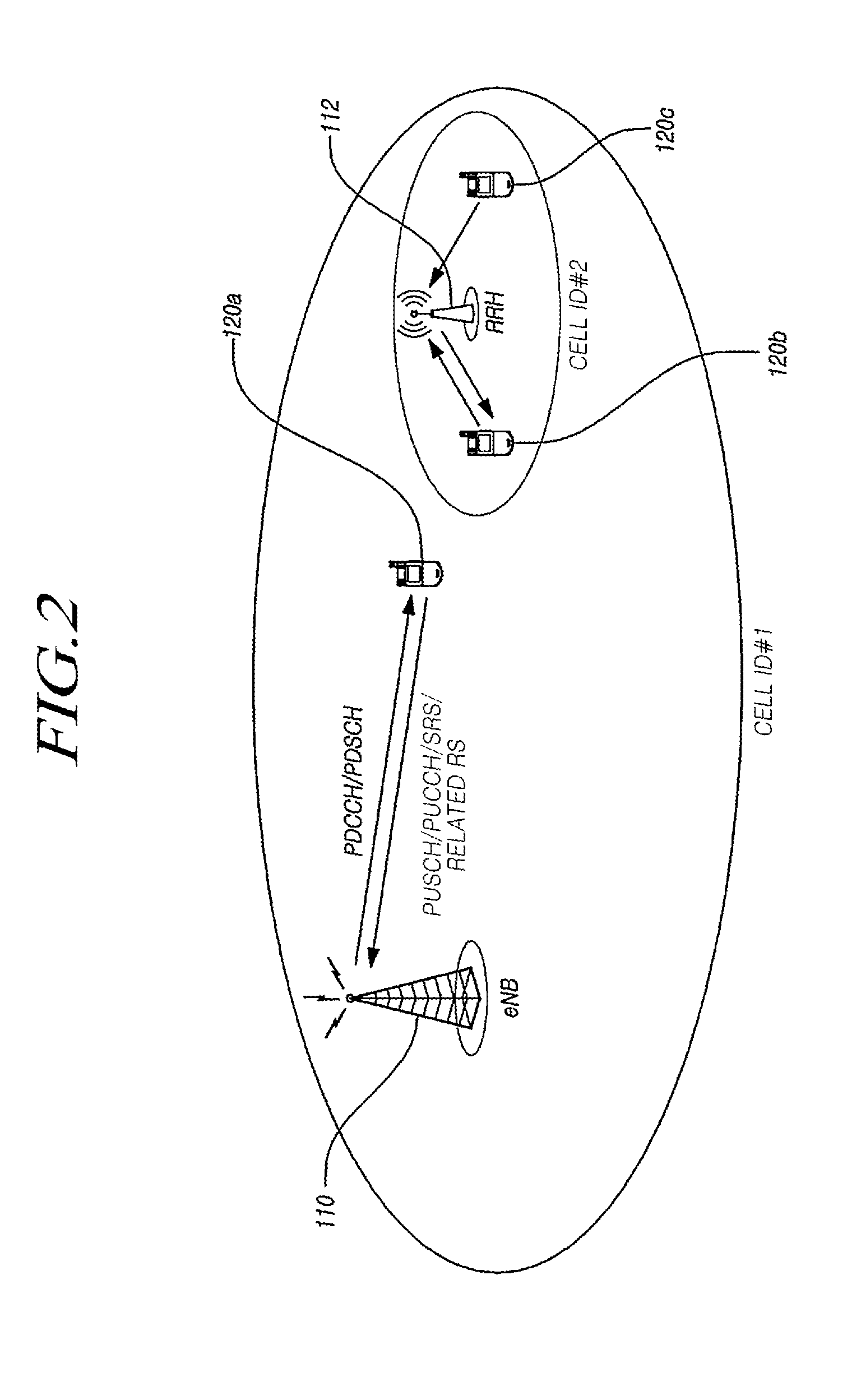
[0163]Referring to FIGS. 1 and 11, a first transmission / reception point, e.g., the eNB 110, which corresponds to a serving cell, searches for at least one transmission / reception point, e.g., transmission / reception points, e.g., a second transmission / reception point, e.g., the RRH 122, which has a probability to transmit a PDSCH to the UE 120 (S1101).

[0164]At this time, a CoMP system according to another embodiment corresponds to the coordinated multi-cell communication system described with reference to FIG. 4, but is not limited thereto. Of course, the number of transmission / reception points participating in coordinated communication may be 4 as illustrated in FIGS. 4 and 5, but is not limited thereto, and may be 2 or 3 or 5 or more. However, for the convenience of the description, the transmission / reception points participating in coordinated communication ...


PUM


Abstract

The present invention relates to a method for transmitting and receiving downlink signal and channel, a terminal therefor and a base station therefor, the method comprising a method for a terminal to transceiver an aperiodic sounding reference signal comprising the steps of: receiving, via a higher layer signaling, two or more parameters for determining a time-frequency resource with which aperiodic sounding signal is transmitted; receiving, via PDCCH and/or EPDCCH, an index designating a parameter set comprising a part of the parameters; receiving, via PDCCH and/or EPDCCH, a signal triggering the aperiodic sounding reference signal; and transmitting the aperiodic sounding reference signal by frequency-hopping to a part of the frequency region within the overall frequency range of interest, frequency hopping being by means of the time-frequency resource corresponding to the parameter received via the higher layer signaling and the parameter included in the parameter set received via the PDCCH and/or the EPDCCH.

Description

TECHNICAL FIELD[0001]The present invention relates to a transmission method and reception method of a downlink signal and channel, a UE thereof, and a base station thereof. Particularly, the present invention relates to a transmission / reception method of a control channel, a transmission / reception method of aperiodic sounding reference signal, and an apparatus thereof, which increase a capacity of a multi-user control channel in a wireless multi-antenna system.BACKGROUND ART[0002]With the development of a communication system, consumers such as companies and individuals use highly various wireless UEs. In current mobile communication systems such as Long Term Evolution (LTE), LTE-Advanced (LTE-A), etc. of the 3GPP family, the development of a technology capable of transmitting high capacity data in accordance with a wired communication network, which corresponds to a high speed and high capacity communication system capable of transmitting / receiving various types of data such as vid...

Claims


Application Information

Patent Timeline
IPC IPC(8): H04W72/04H04L5/14H04L27/26H04L5/00
CPCH04W72/042H04L27/2601H04L5/14H04L5/0048H04L5/0094H04L5/1469H04L5/0035H04W72/23
Inventor KIM, SUN WOO
Owner IUCF HYU (IND UNIV COOP FOUNDATION HANYANG UNIV)
Why Eureka
Try Eureka