
Jig and press-fitting device comprising this jig

Active Publication Date: 2015-10-29
JST MFG CO LTD
View PDF6 Cites 2 Cited by
  • Summary
  • Abstract
  • Description
  • Claims
  • Application Information

AI Technical Summary

Benefits of technology

The patent text describes a jig for inserting press-fit terminals into electronic components. The jig has a movable guide member and a rear surface plate body that guide the press-fit terminals during installation. The jig can be used with different numbers of press-fit terminals and can be fixed to the insertion punch to allow for continuous installation. The jig also has shoulder receiving grooves to support the shoulders of the press-fit terminals and prevent damage. The position of the insertion punch is higher than the movable guide member and rear surface plate body, which prevents buckling of the press-fit terminals during installation. The movable guide member and rear surface plate body can be moved upward and downward with respect to the insertion punch, allowing for repeated installation. The jig can also be used with different types of press-fit terminals.

Problems solved by technology

In this moment, the press-fit terminals, since they have a long length, are buckled and damaged at the middle thereof when the pressing force is applied.
Therefore, the buckling of the press-fit terminals need to be restricted when the press-fit terminals are press-fitted.

Method used


Image

  • Jig and press-fitting device comprising this jig
  • Jig and press-fitting device comprising this jig
  • Jig and press-fitting device comprising this jig

Examples


embodiment

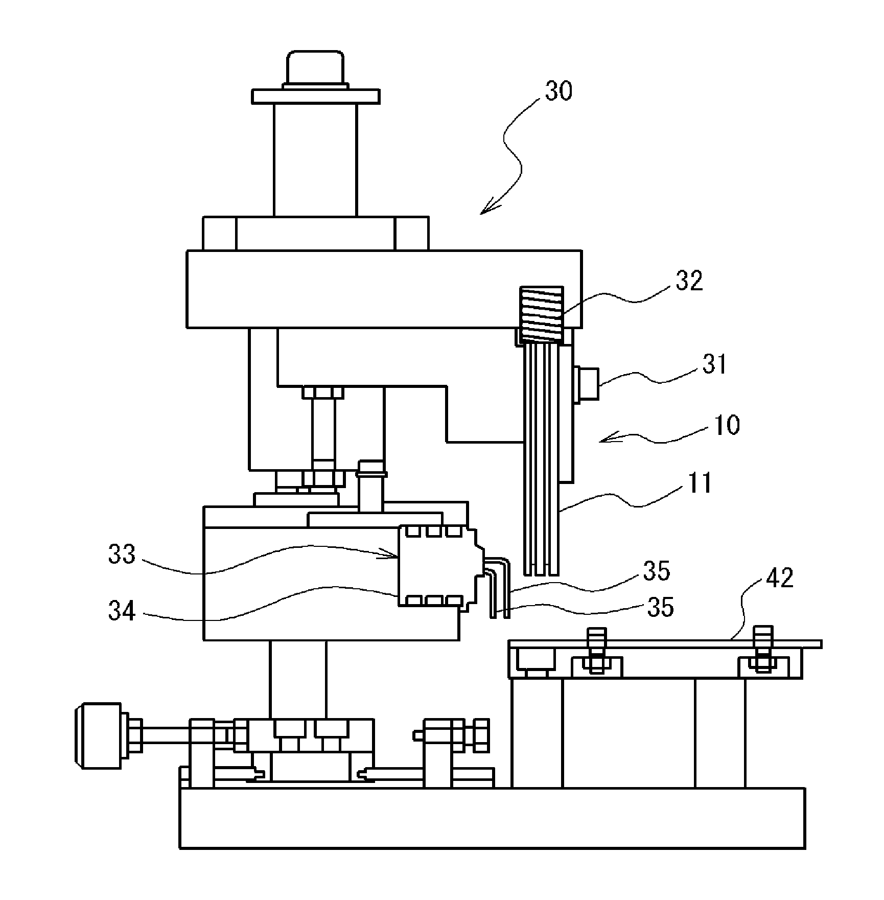
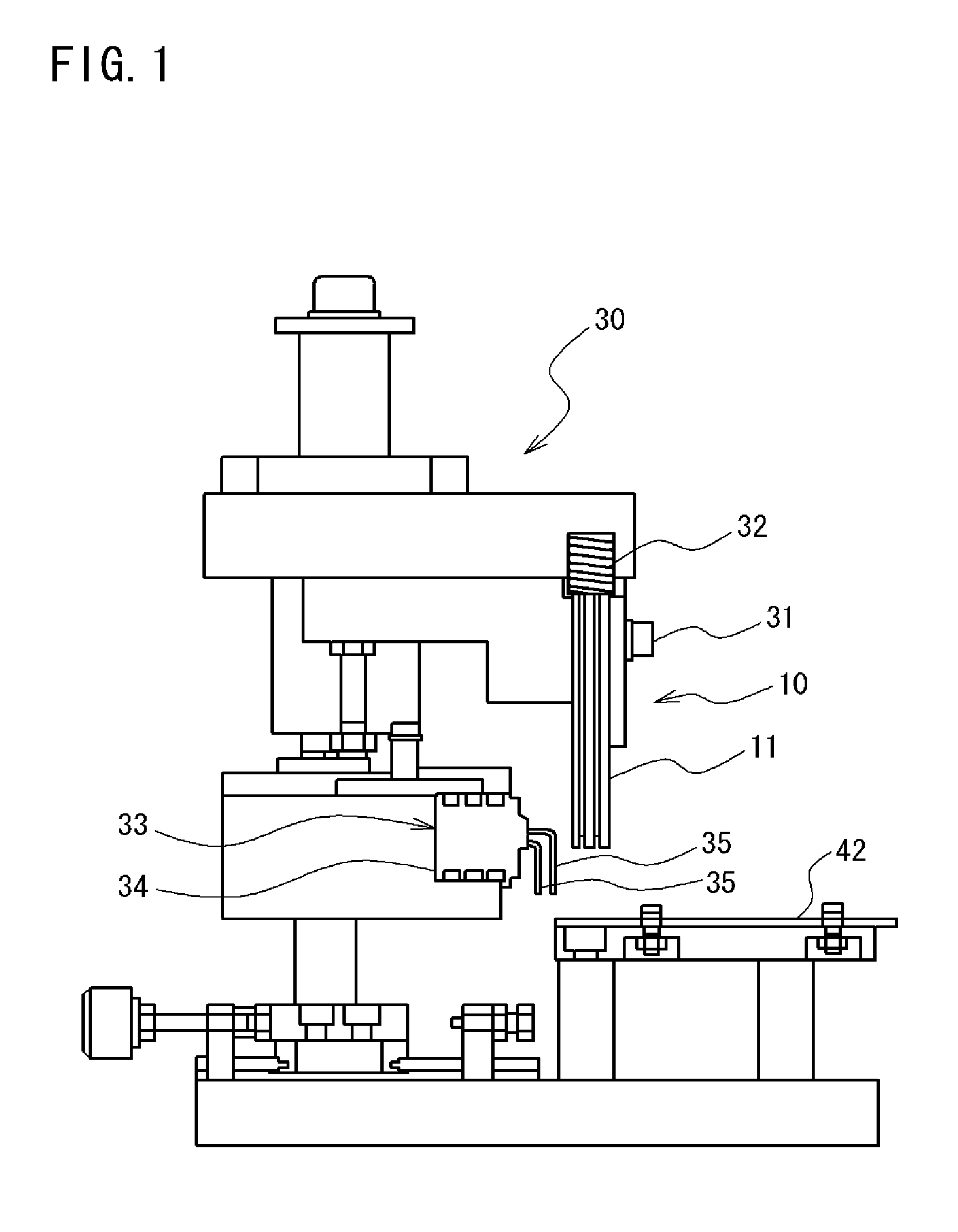
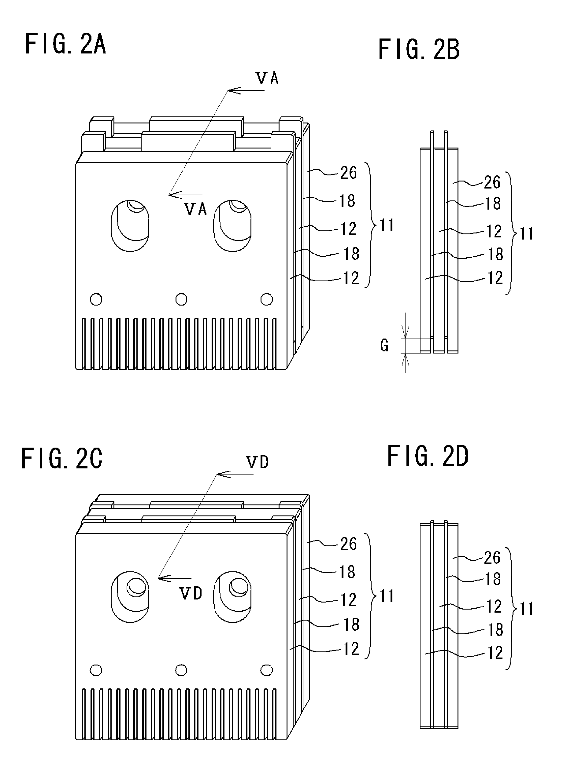
[0049]A jig and a press-fitting device provided with the jig according to the embodiment will be explained with reference to FIGS. 1 to 10. The jig 10 according to the embodiment is, for example, used with being attached to the press-fitting device as shown in FIG. 1, and has a jig unit 11 in which a plurality of plate-shaped bodies are stacked and assembled (refer to FIG. 2). This jig unit 11 is assembled and fixed by making use of at least one fixing member 31. The upper portion of the jig unit 11 is provided with an elastic member 32. The press-fitting device 30 to which the jig 10 attaches is used for press-fitting and installing a connector 33 with press-fit terminals 35 to a member to be installed as shown in FIGS. 1 and 3. In this embodiment, the case in which a substrate 42 is used for the member to be installed will be explained.

[0050]Here, the connector 33 having press-fit terminals 35 to be installed to the substrate 42 by making use of the jig 10 according to the embodim...


PUM


Abstract

Provided are a jig and a press-fitting device that are capable of suppressing buckling during the press-fitting process. The jig has a jig unit in which a plurality of metal plate-shaped bodies for installing a press-fit terminal onto a substrate are combined i.e. it includes: a movable guide member having a guide groove through which a terminal main body can pass; an insertion punch having a punch groove corresponding to the guide groove, and having a pressing section formed therein; and a rear surface plate body. The movable guide member and the rear surface plate body are attached so as to be vertically movable relative to the insertion punch and, while the press-fit section is being press-fitted into the substrate by the insertion punch, the movable guide member and the rear surface plate body move upward relative to the insertion punch after the lower sides thereof abut to the substrate.

Description

TECHNICAL FIELD[0001]This invention relates to a jig and a press-fitting device for installing press-fit terminals having press-fit sections to a member to be installed. More precisely, this invention relates to a jig and a press-fitting device being provided with the jig which can restrict the buckling of the press-fit sections of the press-fit terminals due to the pressing toward the member to be installed during installation.BACKGROUND ART[0002]In order to install the press-fit terminals which have press-fit sections to the member to be installed such as a substrate, a specific jig has been used heretofore. This jig can press the press-fit terminals to fit into the through-holes formed on the substrate by pressing the shoulders for being pressed and formed on one part of the press-fit terminals. In this moment, the press-fit terminals, since they have a long length, are buckled and damaged at the middle thereof when the pressing force is applied. Therefore, the buckling of the pr...

Claims


Application Information

Patent Timeline
IPC IPC(8): H01R43/20
CPCH01R43/205
Inventor ONISHI, JUNJI
Owner JST MFG CO LTD
Learn More