Exhaust gas recirculation system for internal combustion engine

Inactive Publication Date: 2011-01-20
DENSO CORP
View PDF13 Cites 47 Cited by
  • Summary
  • Abstract
  • Description
  • Claims
  • Application Information

AI Technical Summary

Benefits of technology

[0015]The present invention is made in view of the above matters, and it is an object of the present invention to provide an exhaust gas recirculation system

Problems solved by technology

However, in this LPL-EGR system, although the condensed water can be collected, the other solid foreign matters can not be collected.
However, even in this LPL-EGR system, it is likely that solid foreign matters

Method used


Image

  • Exhaust gas recirculation system for internal combustion engine
  • Exhaust gas recirculation system for internal combustion engine
  • Exhaust gas recirculation system for internal combustion engine

Examples


Example

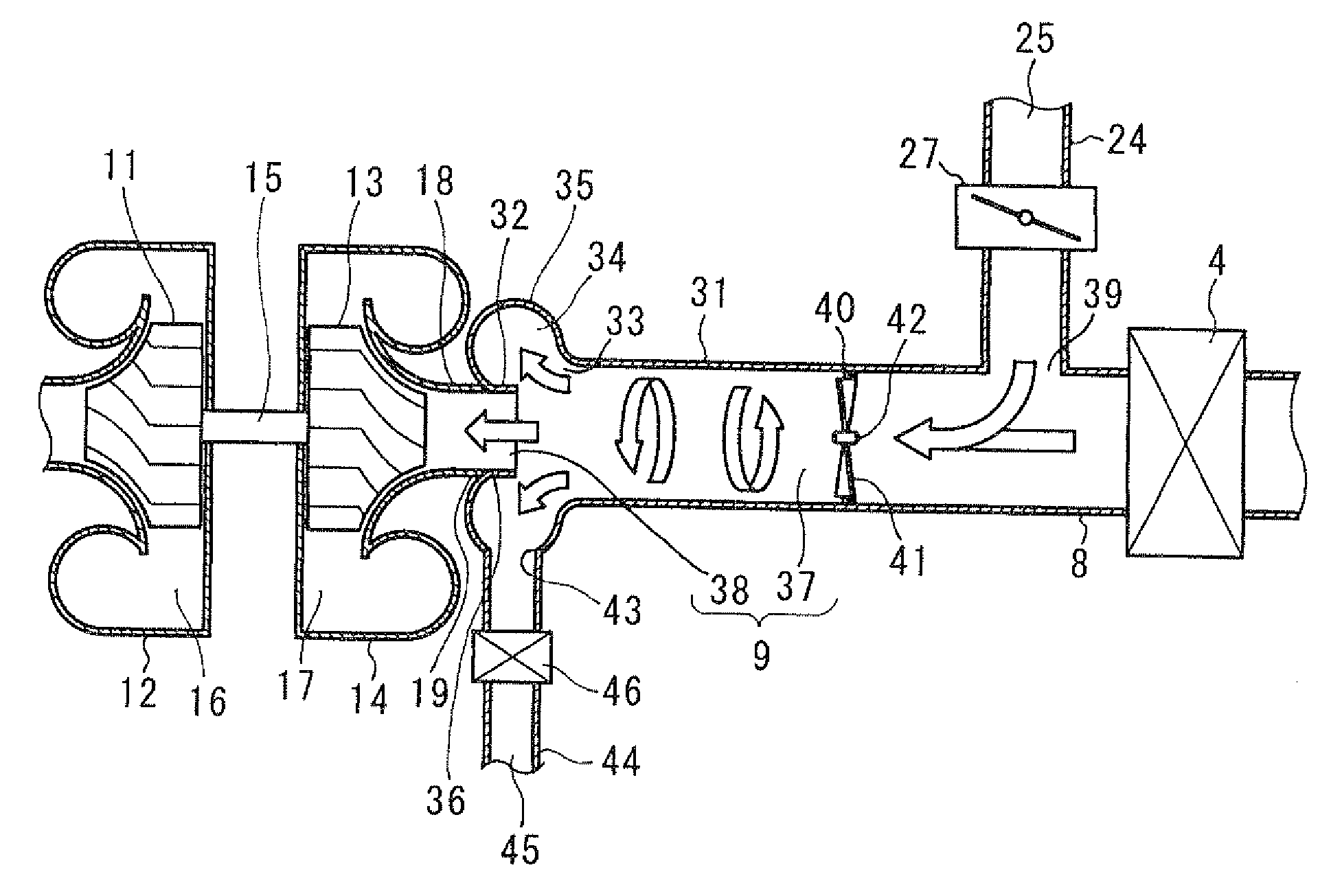
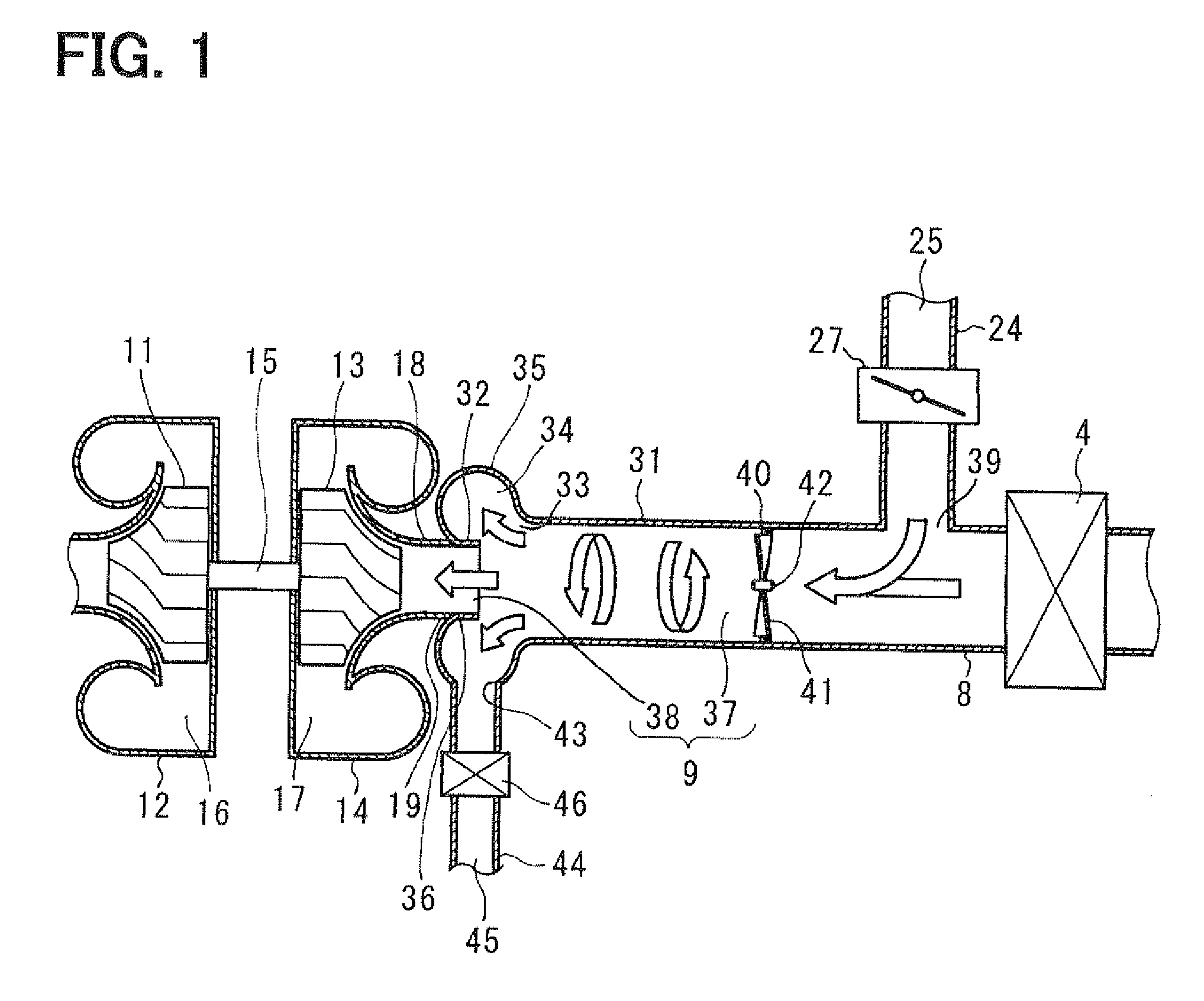
[0039]FIGS. 1, 2A and 2B show a first embodiment of the present invention. FIG. 1 shows an essential part of a low pressure loop (LPL)-EGR system, and FIGS. 2A and 2B show a swirling flow generator.

[0040]According to the present embodiment, an engine control system includes an EGR system and an electronic control unit (ECU). The conventionally common parts and components will be explained based on FIG. 8.

[0041]An engine “E” is a diesel engine having four cylinders, a cylinder block, an intake manifold, an exhaust manifold, and a cylinder head. Four combustion chambers are formed in corresponding cylinder. A piston connected through a connecting rod to a crank shaft is slidably supported in a cylinder bore formed inside the cylinder block.

[0042]The engine “E” has four intake ports and four intake valves. An intake pipe 8 forming an intake passage 102 is connected to each intake port. The engine “E” has four exhaust ports and four exhaust valves. Each exhaust port is connected to an e...

Example

Second Embodiment

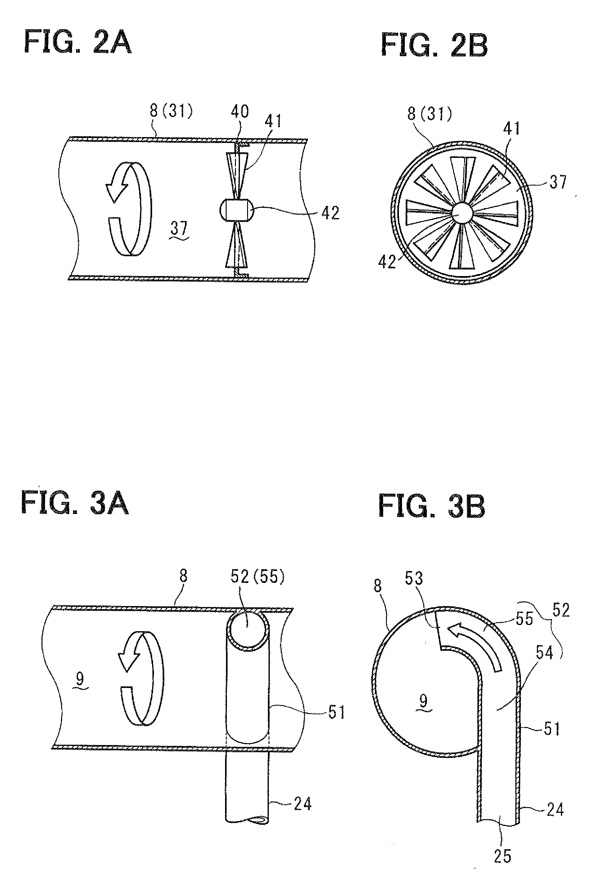
[0068]In the second and the successive embodiments, the same parts and components as those in the first embodiment are indicated with the same reference numerals and the same descriptions will not be reiterated. FIGS. 3A and 3B show a swirling flow generator according to a second embodiment.

[0069]The intake pipe 8 is provided with an EGR introducing pipe 51 connected to the LPL-EGR gas pipe 24. The EGR introducing pipe 51 defines an EGR introducing passage 52 which communicates with the LPL-EGR passage 25, The EGR introducing passage 52 has an EGR introducing port 53 which opens in the intake passage 9. In the present embodiment, the EGR introducing passage 52 corresponds to the swirling flow generator. The EGR introducing passage 52 is comprised of a straight passage 54 and a curved passage 55. The straight passage 54 extends in a tangential direction of an inner wall of the intake pipe 8. The curved passage 55 extends in a circumferential direction of the intake p...

Example

Third Embodiment

[0071]FIGS. 4A and 4B show a swirling flow generator according to a third embodiment. A first introducing pipe 56 and a second introducing pipe 57 are fluidly connected to the intake pipe 8. The first introducing pipe 56 is branched from the intake pipe 8 downstream of the air cleaner 4. The second introducing pipe 57 is connected to the LPL-EGR gas pipe 24.

[0072]The first introducing pipe 56 defines a first introducing passage 61 for introducing the intake air into the intake pipe 8 in a tangential direction of the inner wall of the intake pipe 8. The second introducing pipe 57 defines a second introducing passage 62 for introducing the EGR gas into the intake pipe in the tangential direction.

[0073]The first introducing passage 61 is comprised of a first straight passage 63 and a first curved passage 64 which circumferentially extends along the inner wall surface of the intake pipe 8.

[0074]The second introducing passage 62 is comprised of a second straight passage 6...


PUM


Abstract

An EGR system includes an exhaust gas recirculation pipe recirculating exhaust gas flowing through an exhaust pipe into an intake pipe upstream of a compressor of a supercharger. A swirling flow generator generates a swirling flow of intake air and exhaust gas along an inner surface of the intake pipe in order to centrifugally separate foreign matters from the intake air and the exhaust gas. A foreign-matters-collecting chamber collects the centrifugally separated solid foreign matters therein. The separated solid foreign matters are discharged through a discharge opening and a discharge pipe.

Description

CROSS-REFERENCE TO RELATED APPLICATION[0001]This application is based on Japanese Patent Applications No, 2009-168037 filed on Jul. 16, 2009, No. 2009-177593 filed on Jul. 30, 2009, No. 2009-174046 filed on Jul. 27, 2009, the disclosures of which are incorporated herein by reference.FIELD OF THE INVENTION[0002]The present invention relates to an exhaust gas recirculation system for an internal combustion engine, which recirculates a part of exhaust gas flowing through an exhaust passage downstream of a turbine of a turbocharger into an intake passage upstream of a compressor. Especially, in this system, the exhaust gas introduced into the intake passage is swirled in the intake passage. Its centrifugal force separates foreign matters (particulate matters) contained in the exhaust gas therefrom.BACKGROUND OF THE INVENTION[0003]It is well known that an exhaust gas recirculation system (EGR system) for a diesel engine equipped with a turbocharger. In this EGR system, a part of an exhau...

Claims


Application Information

Patent Timeline
IPC IPC(8): F02M25/07F02B33/34
CPCF02M25/0722F02M25/0724F02M35/084F02M25/0709Y02T10/121F02M26/06F02M26/19F02M26/21
Inventor YANAGIDA, ETSUGOUNISHIO, YOSHITAKAYAMAMOTO, YOSHIAKIOOSHIMA, KIYOSHI
Owner DENSO CORP
Why Eureka
Try Eureka